Electrification of vehicle fleets commonly requires electric vehicle supply equipment upgrades
Learning Objectives
- Understand the reasons behind fleet electrification projects and overview electric vehicle (EV) charger types.
- Identify applicable codes and standards for EV charging systems.
- Understand how networked EV management systems and battery energy storage systems (BESS) can fit into EVSE upgrades.
EV insights
- The foundation for supporting electric vehicles (EV) lies in EV chargers and associated electric vehicle supply equipment (EVSE).
- As the EV market evolves, clients are exploring advanced solutions, including battery energy storage systems (BESS) and networked chargers, to address power distribution challenges and enhance reliability.
![]() In 2022, the motor gasoline and diesel fuel consumption in the U.S. transportation sector accounted for about 30% of total U.S. energy-related carbon dioxide (CO2) emissions, according to the U.S. Energy Information Administration. As government bodies and corporations have begun adopting decarbonization goals, vehicle electrification has been increasingly explored.
In 2022, the motor gasoline and diesel fuel consumption in the U.S. transportation sector accounted for about 30% of total U.S. energy-related carbon dioxide (CO2) emissions, according to the U.S. Energy Information Administration. As government bodies and corporations have begun adopting decarbonization goals, vehicle electrification has been increasingly explored.
Electrification of organization-owned fleet vehicles is a common first step, as it is less administratively challenging than either incentivizing or compelling individual consumers to adopt electric vehicles (EV).
The 2021 Infrastructure Investment and Jobs Act was enacted and included provisions to expand the nation’s network of EV charging stations. Specifically, $7.5 billion of federal funds were allocated for building out the nation’s EV charging network. The law targeted having zero-emission vehicles comprise half of all passenger vehicles sold in America by 2030 and building a net-zero-emissions economy by 2050.
A National Electric Vehicle Infrastructure Formula Program was established under the act to provide funding to states for the strategic deployment of a national network of 500,000 EV charging stations by 2030 and to provide a convenient, reliable and accessible charging experience for all users. The program limits funding to projects that are directly related to the charging of a vehicle and only for EV charging infrastructure that is open to the public or to authorized commercial motor vehicle operators from more than one company.
The infrastructure must also be installed, operated and maintained by qualified personnel. Other stipulations of the program include interoperability across the nation of EV charging infrastructure including data collection, network connectivity and providing information to the public on the availability of EV chargers such as locations, pricing and accessibility.
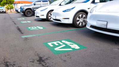
As these targets and programs continue to mount, an increasing number of clients are looking for guidance on how to comply with various goals and seeking the design of electric vehicle supply equipment (EVSE) upgrades (see Figure 1).

Electrical codes and standards
Electrical design requirements for EVSE are defined by NFPA 70: National Electrical Code. Additionally, a wide variety of other standards also govern the design of EVSE, such as those listed below. Given the evolving landscape of EVs, standards developing organizations (SDO) are largely still reacting to technological developments pushed by vehicle manufacturers.
- American National Standards Institute.
- International Building Code.
- International Fire Code.
- International Mechanical Code.
- IEEE.
- National Electrical Manufacturers Association.
- NFPA 1: Fire Code.
- Occupational Safety and Health Administration.
- SAE International.
- Unified Facilities Criteria.
- UL Solutions.
- Local codes and owner’s design guidelines.
The 2023 edition of NFPA 70: National Electrical Code (NEC) defines EVSE under Article 625 as,
“The conductors, including the ungrounded, grounded and equipment grounding conductors and the electric vehicle connectors, attachment plugs, personnel protection system and all other fittings, devices, power outlets or apparatus installed specifically for the purpose of transferring energy between the premises wiring and the electric vehicle.”
This definition includes what is commonly referred to as “EV chargers” where the vehicle plugs in and all dedicated upstream electrical equipment servicing the EV charger.
It shall be noted that this definition does not require EVSE to be able to receive power from an EV. That equipment category is separately defined in the NEC as electric vehicle power export equipment (EVPE). EVSE and EVPE requirements can be met by a single piece of equipment, which is sometimes referred to as bidirectional EVSE.
Exporting power from EVs for use elsewhere remains an emerging technology with incomplete oversight from regulators and SDOs. Vehicle-to-grid, vehicle-to-home, vehicle-to-load and vehicle-to-vehicle are all related applications of this concept. EVPE and EVs could serve as a powerful network of distributed energy resources (DER) to improve grid resiliency, perform demand response and provide backup power to individuals.
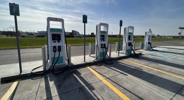
As examples of developing standards, IEEE 1547 and IEEE 2030 establish criteria for interconnecting DERs more broadly, and UL 1740 and UL 9741 establish criteria for EVPE safety and functionality. Overall, most EV chargers and supporting infrastructure being deployed meet the criteria for EVSE, but not EVPE (see Figure 2).

EV charger types and levels
EV chargers and supporting EVSE are the foundation required to support a fleet of EVs and ensure that vehicles can charge in a manner consistent with their required use patterns. There are different technologies for EV chargers: Level 1, Level 2 and Level 3 or direct current fast charging (DCFC) chargers, each of which has different power input requirements and subsequent impacts on a facility’s electrical system.
Level 1 (L1) chargers are the slowest chargers and work with a standard wall outlet. These chargers use a standard 120-volt (V) alternating current (ac) dedicated branch circuit, typically rated for 15 or 20 amperes.
Level 2 (L2) chargers are the most deployed type of charger for applications requiring daily vehicle use. L2 chargers have an input voltage of 208-240 Vac and can deliver between 3 to 19 kilowatts (kW) of power. As standards are updated, the specific power output requirements of L2 chargers should become better defined.
Many charging station manufacturers have L2 charger options as either single- or dual-dispenser, with two EVs being able to plug into one dual-dispenser charging station. In some applications, it is more economical to deploy dual-dispenser chargers depending on mounting costs and required site rework for each installation (see Figure 3).

Level 3 (L3) or direct current fast chargers (DCFC) are the fastest type of EV chargers currently available and have the highest power capabilities of up to 350 kW. DCFC generally require 208 or 480 V, three-phase ac power and can typically charge at a rate of 50-60 kW. A DCFC can recharge an EV at a rate of 3 to 20 miles of range per minute. See Table 1 for detailed information on typical charging rated by EV charger level.
EV charging connectors
SAE International, formerly the Society of Automotive Engineers, is a U.S.-based professional and standards-developing organization focused on motor vehicle components. In addition to providing standards for rating automobile horsepower, the organization has also developed and published standards on EV charging connectors.
The SAE J1772 connector has emerged as the most common EV car plug for L1 and L2 charging in the United States. Tesla is the significant exception due to its use of the North American charging standard (NACS). The NACS was formerly a proprietary connector and now is being standardized under the name SAE J3400. This connector will be backward-compatible with Tesla vehicles and will also be able to support an emerging 800 V battery architecture, which the original connector could not. However, an SAE J1772 adapter is currently included with every Telsa vehicle.
The combined charging standard (CCS) connector has emerged as the most common connector for DCFC. The “combined” portion of the CCS namesake derives from the connector’s ability to support L1, L2 and L3 charging as it uses several of the pins from the J1172 port. NACS connectors can also support L1, L2 and L3 charging.
Non-Tesla EVs can sometimes charge via a Tesla charging station using an adapter. These adapters historically would not work at Tesla’s DCFC stations or “Tesla Superchargers,” which were designed for sole compatibility with Tesla vehicles.
However, in early 2023, Tesla began deployment of a proprietary dual-connector “Magic Dock” adapter at a small number of North American Supercharger locations. The Magic Dock can use either a NACS or CCS connector and allows non-Tesla EVs to charge at the Tesla Superchargers. Additionally, Ford and General Motors have recently announced their intent to use exclusively NACS from 2025 onward, a development that could spur broader shifts in the industry from CCS to NACS.
Design considerations
As EVs become more prevalent, their associated electrical demand might strain existing power distribution systems and force upgrades. In July 2022, Texas underwent a heat wave predicted to tax the utility grid beyond its capacity. The Electric Reliability Council of Texas, which operates the state’s grid, called on residents to conserve energy to stop the grid from being pushed to near-emergency conditions. Tesla told users not to charge their cars at peak hours during this time and even offered incentives to their clients to charge their cars during off hours.
Increased demand and extreme weather conditions are a common factor in issues with the power grid across the country. The utility grid will be pushed to limits not seen before with the introduction of large-scale charging systems and historical load profile data is not available for utilities to rely upon. Detailed load studies will help the utility understand the unique load profile of EVSE and identify upgrades required to distribution infrastructure to support further build-out of EVSE infrastructure.
On the customer’s side of the meter, NEC Article 220.87 requires a load study to be performed before adding equipment to an electrical system to protect against potential system overload. If the maximum demand data for a one-year period is not available, the calculated existing load shall be permitted to be based on the maximum demand continuously recorded over a minimum 30-day period. This 30-day period is to be measured using a recording ammeter or power meter connected to the highest loaded phase of the feeder or service, based on the initial loading at the start of the recording.
The recording shall reflect the maximum demand of the feeder or service by being taken when the building or space is occupied and shall include by measurement or calculation the larger of the heating or cooling equipment load and other loads that may be periodic in nature due to seasonal or similar conditions. Figure 4 shows a temporary meter installation in accordance with the NEC requirements.

Additional load from EVSE, especially during times of peak grid demand, may lead to an unstable grid. Electric utility companies are working to upgrade their distribution systems, but this is an enormous task based on the condition and breadth of the infrastructure system. Solutions are needed in the interim to mitigate the impact on existing power distribution systems. Alternatives to accommodate the increased electric demand that charging during on-peak times will add to overall peak demand include the use of networked EV chargers and battery energy storage systems.
Networked EV chargers allow the system owner to monitor and control charging events remotely, view usage of statistics and report issues. All charging stations are connected to the charging platform and can communicate with each other.
A charging platform is software that provides real-time information for the monitoring and optimization of EV charging networks. Using a charging platform, the stations can be grouped to allow for stack management that can limit the charging power of a group so as not to exceed the electrical capacity of the system. If the maximum charging power set for the station group is momentarily exceeded, the charging power can be programmed to drop down automatically at all stations in the group or to prioritize charging certain loads and drop other loads entirely.
Another alternative to lower electricity bills is to use renewable energy sources and batteries. Battery energy storage systems (BESS) are devices that enable energy to be stored and then released when a system owner needs power most. Intermittent power sources including renewables such as solar photovoltaic (PV) and wind can be made dispatchable at any time through the implementation of a large enough BESS.
On-site batteries can charge and discharge using direct current (dc) and connect to the electrical system through inverter(s), which convert from dc to ac power. Additionally, the BESS can charge from the electrical system at times when electricity costs are lower if the utility offers time variable pricing rates. Power is then stored and released later when demand is higher, a practice known as “peak shaving.” Peak shaving reduces demand on the power distribution system and enables reliable and fast charging without increasing demand charges from utility.
BESS is a mature market in many parts of the world such as the United States. Electrify America has deployed more than 150 BESS solutions across the Americas and is aiming to expand its network to 10,000 chargers by 2026.
BESS technology is available, but it comes with advantages and disadvantages. Beyond its use to reduce overall cost of EV operations, it also has several other advantages including improving the reliability of the charging system by providing a stable power source, reducing the risk of power surges and providing backup power in case of utility failure.
There are also several drawbacks when implementing BESS solutions. These include added cost of purchase and installation included with the charging systems. There can also be costs associated with the additional space these systems require (land acquisition) and the maintenance costs associated with the operation of these systems. As with any type of battery or battery system, there are inherent risks associated with their use, which include electric shock, fire, explosions, flash burns and exposure to hazardous chemicals among others. Precautions will be required to protect the system and the users.
An example of how a BESS could work is as follows: A station owner installs a battery system capable of charging and discharging at 150 kW of power and with a battery capacity of 300 kWh. When no vehicles are present, the BESS charges from the grid to ensure that on-site energy is available, avoiding a potential higher demand charge when more power is needed.
When a vehicle arrives, the battery can deliver electricity at up to 150 kW without drawing power from the electrical grid. If more vehicles arrive, the power delivered to the charging vehicles can be split between the BESS and the utility source, if needed. A battery with a 300-kWh capacity could sustain the peak demand through several vehicle charges and recharge in between keeping the peak demand below 150 kW. In either case, the cost of system operation is reduced because the cost of the electricity and the demand charges are greatly reduced.
Clients are increasingly exploring BESS for various applications due to recent technological shifts, improvements in cost and environmental considerations. Innovations in battery chemistries and efficiencies have improved the capacity and reliability of BESS and DERs have become more prevalent with the emergence of microgrids and decentralized renewable generation technologies.
Battery systems can play a key role in integrating DERs into the grid. As BESS becomes a more mature technology, system costs have continued to decline, making them more economical. Government initiatives and incentives also continue to be major influencers in the deployment of these systems.
Demand management and access control
A networked management system offers various levels of communication with the system owner. Communication is achieved through a wireless or hard-wired connection to an EV charging management platform usually located in a control room or server room. A strong and reliable 4G signal is required for wireless communication. A charging management platform provides real-time data from connected charging devices and relays charging events to the owner of the charging stations, which allows the system owner to monitor, manage and restrict the use of their devices remotely to best fit their use case.
Networked management systems can be implemented so that all pieces are fully owned and operated by the system owner if they have the resources for the system design and software development/maintenance. However, it is often more economical for system owners to use vendor-package systems. Open charge point protocol (OCPP)-based networks give both the charging station owner and customer choices and flexibility
OCPP is an open-source communication standard that allows for interoperability between equipment vendors, in contrast to a proprietary system. The OCPP community continuously updates application software features to accommodate emerging technologies and evolving standards. This allows owners of charging stations the ability to switch between OCPP providers if needed. It also allows the customer the flexibility to use any network charger encouraging competitive pricing, features and service.
An energy management system as defined by NEC Article 750 is a system consisting of a monitor(s), communications equipment, controller(s), timer(s) or any other device(s) that monitor and/or control an electrical load or a power production or storage source. This demand load management can also be accomplished through a networked management system, which will allow the system to optimally distribute the available power based on criteria set by the owner. It may monitor and control electrical loads for the purpose of load shedding, disconnection of power and limiting the capacity of a branch circuit, feeder or service to assure the circuit is not overloaded at any time.
There are restrictions when this type of energy management system can be used, but EV charging does not fall into those categories. EV charging load management balances energy demand throughout the day and can focus on reducing energy usage during peak demand. When multiple charge points are in use, it can balance the power delivery among them to ensure that vehicles can be charged in the way that best serves the owner or drivers.
Many utility companies offer demand-response programs where system owners can receive rebates for reducing electrical demand during peak demand time windows, another potential benefit to the system owner. Communication with a 4G network is required to allow for participation in utility rebates.
Reservation parameter control defines what a reservation is and the policies surrounding it. Parameters that the system owner can control include automatic charger shut-off when the battery is full, if a vehicle remains in the spot past the user’s reservation window and penalties for a reservation no-show and user tardiness, such as a late start or late end within the reserved time window.
Access control refers to the system owner’s ability to restrict EV drivers who are not part of the program from viewing their charging stations. This could be possible by creating a geofence around each group of chargers or requiring user authentication via an email address to sign up for the app or view stations. Access control parameters are important to allow employee, visitor and valid guest use without permitting the public to see the stations.