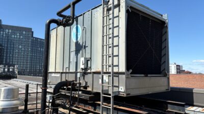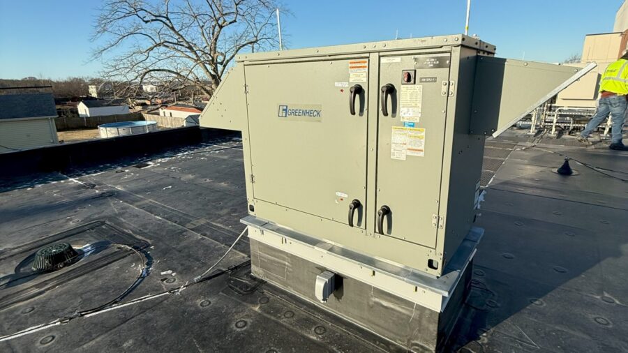
HVAC/R and Mechanical
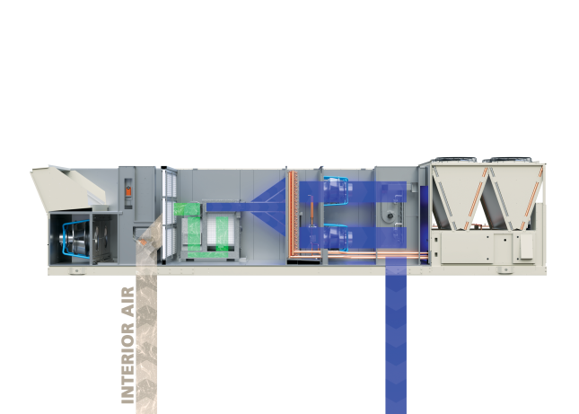
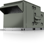
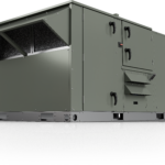
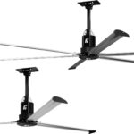
Heating, ventilation, air conditioning (HVAC) and refrigeration provide indoor comfort for buildings. Products and systems typically are specified by mechanical engineers to meet certain heating, cooling, energy efficiency, indoor air quality, refrigeration or other needs.
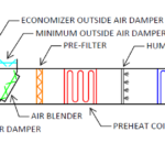

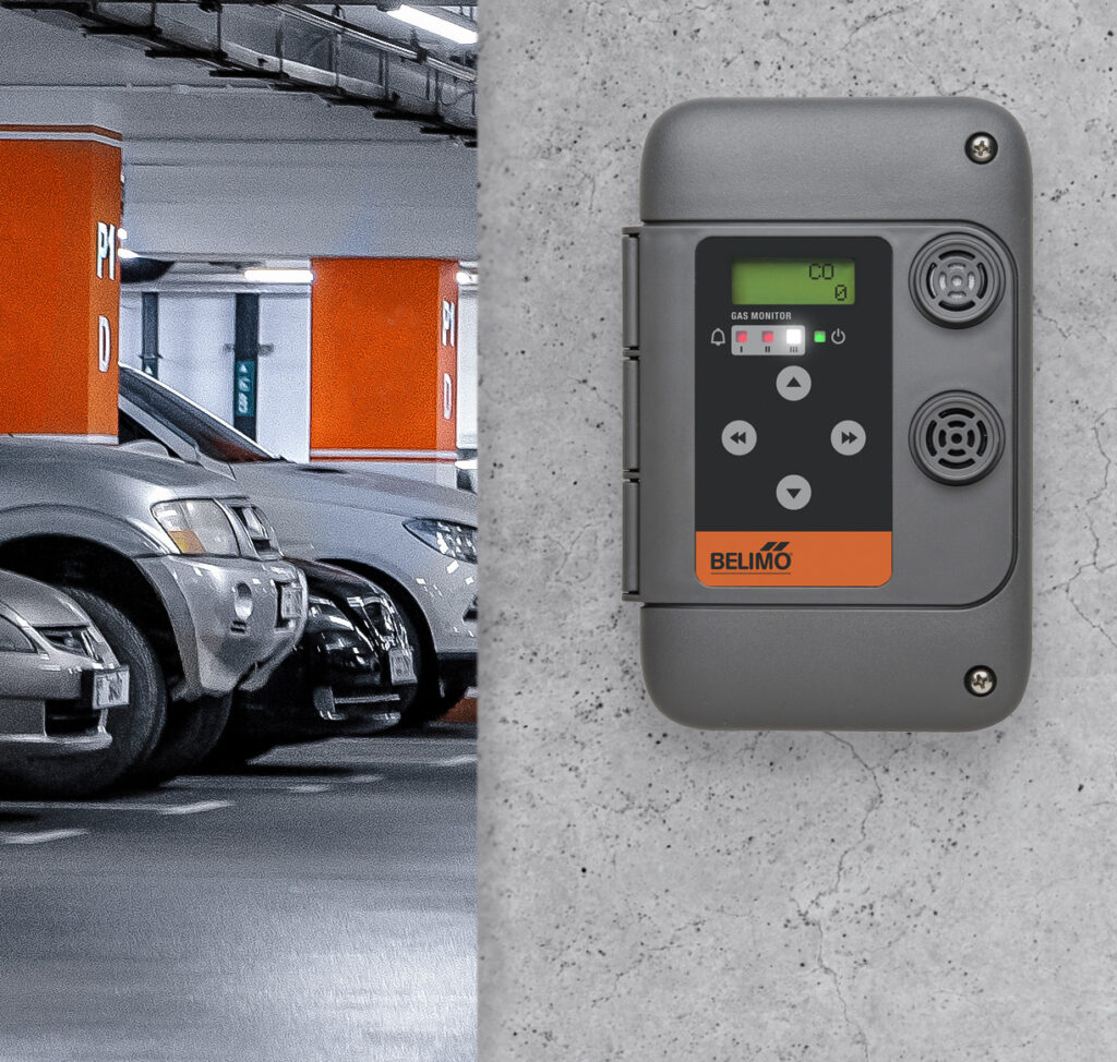
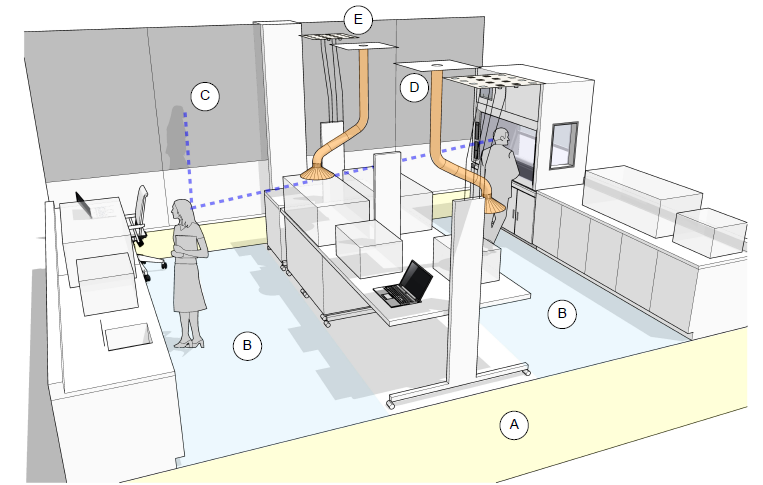
Air Quality
More Like This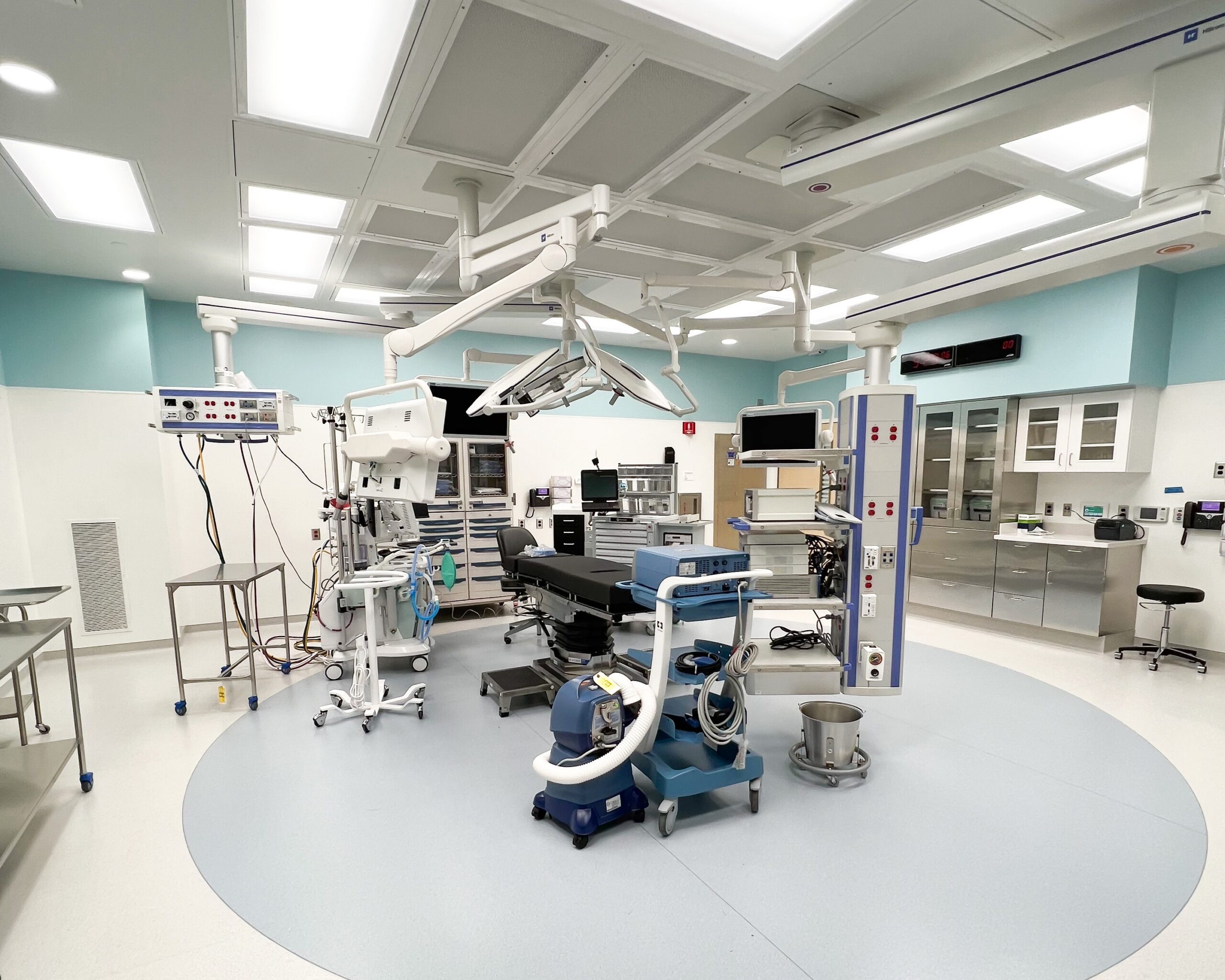
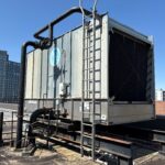
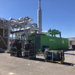
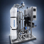
Boilers, Chillers
More Like This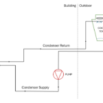


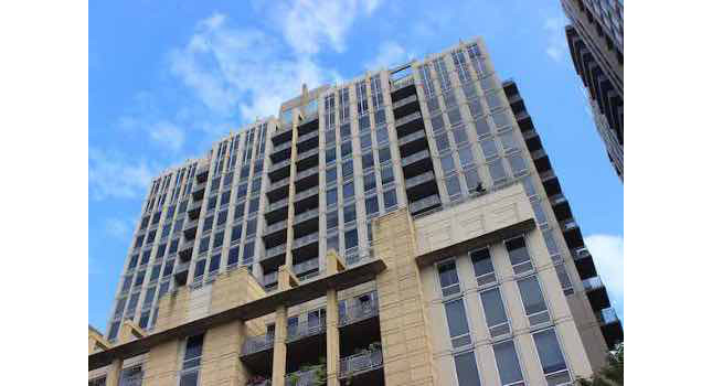
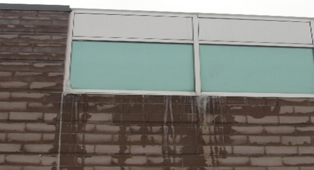
Building Envelope
More Like This

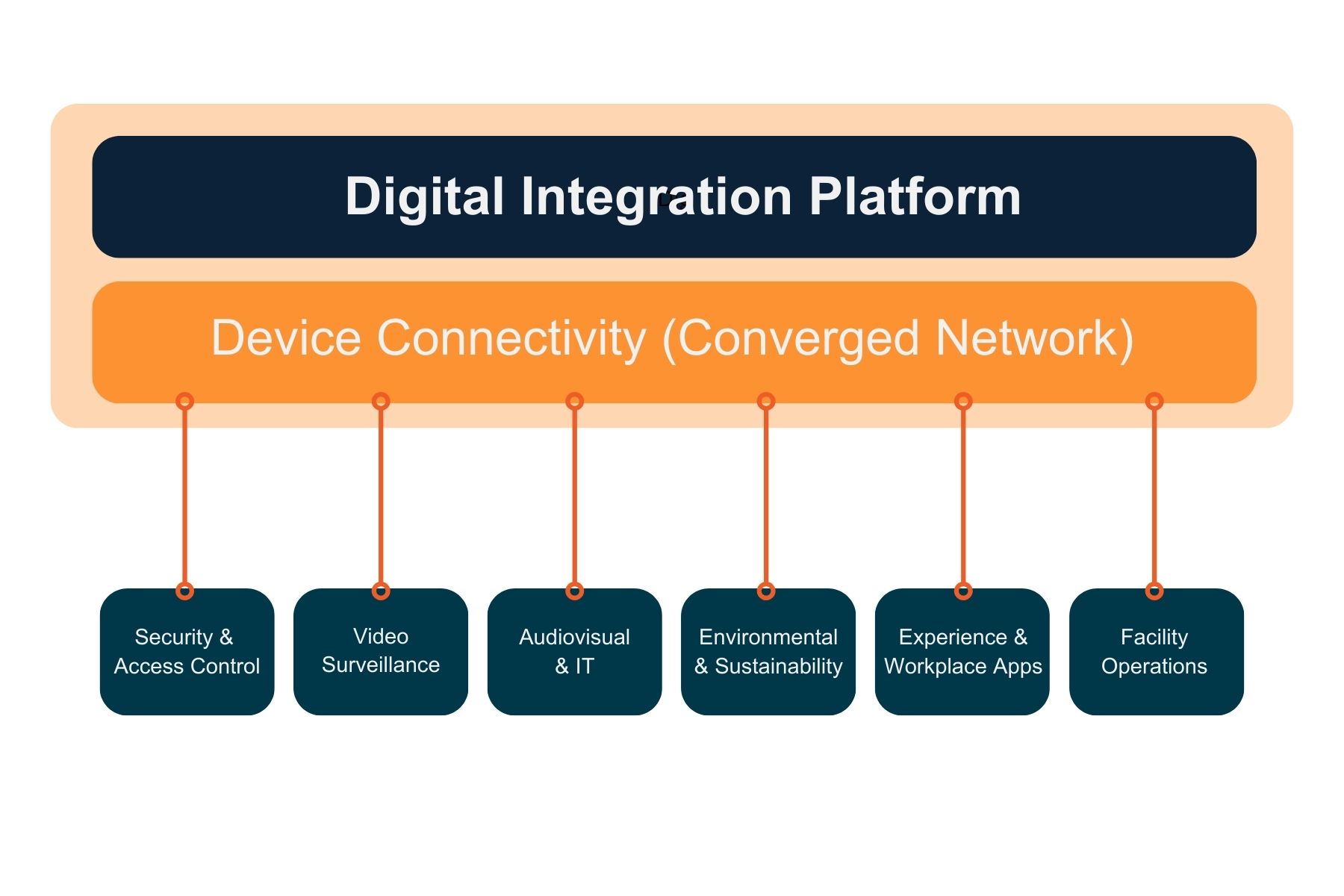
Building Integration System
More Like This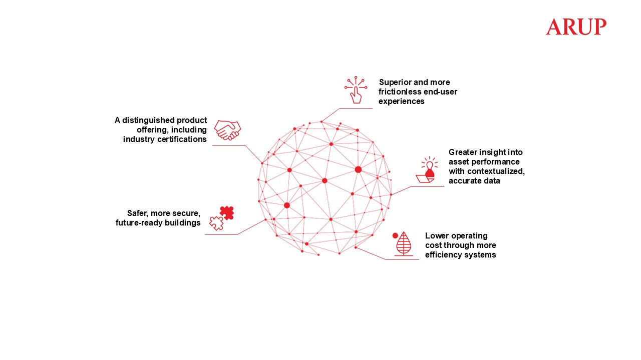
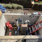
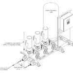
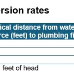
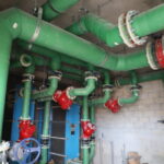
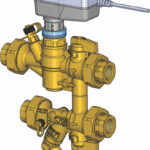
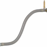
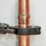
Plumbing, Pumping and Pumps
More Like This
Related Products

HVAC/R and Mechanical Continued