Chillers and cooling towers are increasingly being applied in new ways to provide electrification of building heating systems.
Learning objectives
- Understand the basic design considerations for cooling towers and chillers.
- Learn about opportunities to provide heating using a chiller heater.
- Review principles of energy analysis applied to evaluate building electrification, including calculation methods required to measure decarbonization.
Chiller insights
- The project proposal explores the potential cost savings and process of replacing a gas-fired boiler system with a rooftop air-source chiller and water-cooled heat pumps, using a closed cooling tower and upgraded structural and electrical infrastructure to support the new chiller while eliminating on-site combustion.
- Through window replacement, high-efficiency heat pump technology and the electrified chiller system, the improvements reduce energy consumption, lower operating costs and cut carbon emissions while positioning the chiller-based design to benefit from ongoing grid decarbonization.
Modular chiller and heat pump systems — often referred to as “chiller heaters” — provide both heating and cooling. Chiller heaters are air-cooled heat pump chillers that heat buildings with electricity. The chiller heater is installed outdoors and draws heat from the ambient air to heat water through the reverse refrigeration cycle.
Through this modeled project, explore how a chiller heater system and associated cooling tower could potentially replace a gas-fired boiler heating system in an existing New York City building.
Cooling tower location
Cooling towers are typically located outdoors — either on the roof or on the ground, however, they can also be located inside the building with a connection to the outside air.
Many factors influence the location of the cooling tower, including the availability of space. In cities or congested areas, cooling towers are often located on the rooftops of buildings.
When rooftop placement is selected for a cooling tower, close coordination with the building structure is essential to ensure the building’s framing can support the tower’s weight.
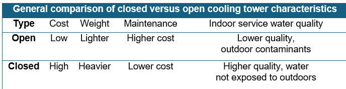
Closed versus open cooling towers
Open cooling towers expose the system water to the outside air by circulating water over fill components within the tower to evaporatively cool the water temperature. The fill includes internal media components that maximize the contact surface between water and outside air to transfer heat from the water to the outside air.
In contrast, closed cooling towers do not expose system water to the outside air. The system water is circulated through a coil inside the cooling tower and is cooled by water circulated over the coil within the cooling tower.
Open cooling towers generally incur greater maintenance costs due to increased water‑treatment requirements. Closed towers have higher initial purchase costs and typically weigh twice as much as comparable open‑tower units. As a result, open towers are typically selected when the water from the system may be exposed to the outside air (see Table 1).
Air-cooled chillers
Air-cooled chillers can operate as cooling-only units or in a heat pump configuration, which heats and cools the service water for the building. Air-cooled chillers may be located outdoors on the roof or on the ground, however, these are typically not located inside a building, as the design of many air-cooled chillers require an outdoor location.
Many factors influence the location of the chillers. Like cooling towers, their location is primarily determined by the availability of space. Consequently, buildings in dense urban areas often require that the air-cooled chiller be located on the rooftop.
Rooftop chiller placement must be closely coordinated with the building structure to verify that the building framing can support the chiller’s weight.
Electrification of a building with a chiller heater
This model focuses on the exploration of retrofitting a gas-fired boiler system with a chiller heater and cooling tower design to identify potential cost savings. The building in this proposal is five stories tall and consists of approximately 80,000 square feet of mixed-use occupied space. The building’s main condenser water pipes connect the rooftop open cooling tower to water-cooled, floor-mounted, vertically configured air conditioner units inside the building. A gas-fired boiler located in the basement generates hot water that flows through piping to radiators along the building’s perimeter walls, heating interior spaces.
The building owner requested that a new system use grid electricity to eliminate on-site fuel combustion and reduce the building’s carbon footprint.
The water-cooled air conditioner units are in mechanical rooms throughout the building. Discharge air ductwork connects the units to the conditioned spaces. Each unit system’s discharge ductwork includes an electric resistance duct heater located downstream of the unit. These systems supply air through the discharge ductwork to heat or cool the spaces, with the duct heaters supplementing the heat provided by the perimeter radiators. Air supplied to spaces returns to the unit intake through plenum grille openings in the mechanical room walls.
Ventilation air is supplied by a roof-mounted fan and delivered through ductwork to discharge grilles in the mechanical room, which serves as the unit’s return plenum. The systems are controlled by wall-mounted thermostats. The water‑cooled condensers reject heat into the condenser‑water loop, which carries the warmed water to the rooftop open cooling tower.
At the tower, the water discharges at the top and sprays over the internal fill, where heat is transferred to the air drawn through the tower by the fan. The cooled water collects in the basin sump and is subsequently pumped back to the air‑conditioner units, thus completing the cycle.
The existing windows are operable and in poor condition. Some existing windows do not fully close, leaving the perimeter wall poorly insulated and resulting in significant heating losses.
The perimeter windows, cooling tower, boiler and air conditioner systems require replacement due to condition and age.
Decarbonize, electrify and replace
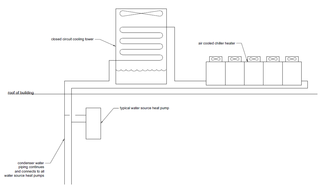
The proposed system was designed to replace the air conditioners with water-cooled heat pumps and adds a chiller heater on the building’s roof. The open cooling tower is to be replaced with a closed tower and the boiler and perimeter heating are to be eliminated from the building (see Figure 2).
Due to the improved insulation performance of the new perimeter windows, perimeter radiators may be eliminated without negatively impacting occupant comfort. The chiller heater adds heat to the water, which the airside heat pumps draw from to heat the space in lieu of the heat provided by the removed radiators.
Building emissions are calculated based on the amount of energy and type of fuel consumed and measured in metric tons of carbon dioxide equivalent (tCO2e). To calculate building emissions, the type of fuel consumed is multiplied by the emitted tCO2e. The tCO2e emitted per kBtu (1,000 British thermal units) of the fuel is known as the greenhouse gas coefficient. Natural gas combusted on the premises results in a greenhouse gas coefficient of 0.00005311 tCO2e per kBtu.
It is important to note that the greenhouse gas coefficient for natural gas will not change, as the emissions from combusting a kBtu of natural gas on the premises will not change. Through renewable energy sources and improved efficiency, the greenhouse gas coefficient of utility electricity will decrease as the electricity grid produces fewer emissions per kilowatt hour.
New York City’s greenhouse gas coefficient for electricity was 0.000288962 tCO2e per kBtu at the time of this analysis. The city will decrease its greenhouse gas coefficient per its plan to transition to a cleaner energy grid by 2050 as detailed in the New York City’s Roadmap to 80 x 50.
Energy efficiency analysis
Energy efficiency analysis of the new electric heat pump and chiller heater system, combined with new perimeter windows, indicates that the modeled system would reduce overall energy costs.
Energy consumption is reduced through the combined effects of the new windows’ improved thermal insulation performance, increased efficiency from the air source chiller heater replacing the noncondensing gas-fired boiler, installation of new heat pumps in place of air conditioner units and the elimination of electric resistance supplemental duct heaters. Together, these changes reduce total energy consumption resulting in cost savings despite the higher expense of electricity compared to natural gas.
Natural gas appliances are unable to achieve 100% efficiency as they only draw heat energy from combusted fuel. Noncondensing boilers, for example, typically operate at roughly 80% efficiency. In contrast, air source heat pumps like the chiller heater draw heat energy from electricity and ambient outside air, outputting more heat energy than the equivalent of the electricity consumed. Depending on conditions, air source heat pumps may provide up to four times the efficiency of an equivalent electric-resistance boiler. The chiller heater is also designed to continue heating at low ambient temperatures expected in the region (see Table 2).

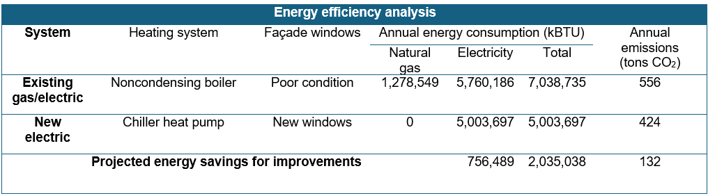
Utility meters measured the annual energy consumption of the existing building to be 5,760,186 kBtu of electricity and 1,278,549 kBtu of natural gas. An energy efficiency analysis of the proposed building improvements, including new windows, heat pumps, chiller heater and cooling tower, estimates a new annual energy usage of 5,003,697 kBtu and the elimination of natural gas consumption. Domestic water heat pumps will be provided for plumbing fixtures.
The new system will provide annual energy savings of 2,035,038 kBtu of electricity. The elimination of 1,278,549 kBtu of natural gas and the 756,489 kBtu reduction of electricity results in approximate savings of 132 tCO2e, based on NYC’s greenhouse gas coefficients for 2024-2029 (see Table 3).
The building owner requested to explore this design to electively decarbonize the building, but these modifications would also make the building compliant with New York City’s Local Law 97, which limits the carbon footprint of buildings.
Adding a chiller heater to an existing building
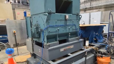
The new chiller heater would require rooftop space for installation. The design team must consider a multitude of factors, including the weight of the chiller, connection points to the existing structural framing of the building, support framing of the chiller unit, roof weatherproofing details, proper service clearance required by the manufacturer, discharge sound considerations and a clear path for the piping that connect the chiller to the building.
Structural engineers review the installation of the new chiller by assessing the loads imposed on the existing building framing and determining the acceptable connection point to support the new equipment. The structural engineer requires drawings of the building’s existing framing for this determination. If the drawings are unavailable, the structural engineer will need to see the existing framing exposed through probes of the existing structure.
In this case, the design team was able to obtain existing drawings of the building’s framing from the city’s department of buildings. Architects and structural engineers also provide waterproofing details for the connection of new support steel through the existing roofing membrane to the building’s existing framing.
It was also confirmed that the discharge sound from the new equipment is acceptable. In New York City, sound levels must meet the requirements of the Department of Environmental Protection; the design engineer specifying new chillers is responsible for confirming that discharge sound is acceptable to authorities having jurisdiction. Vibration isolators were also specified to support the new chiller heaters.
While this building does not require seismic support, designers should always verify whether it is needed, as seismic requirements must be included in the specification of vibration supports. Vibration isolation at the connection to building framing minimizes vibration-related noise in the occupied spaces of the building.
Cooling tower as a replacement
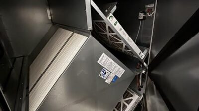
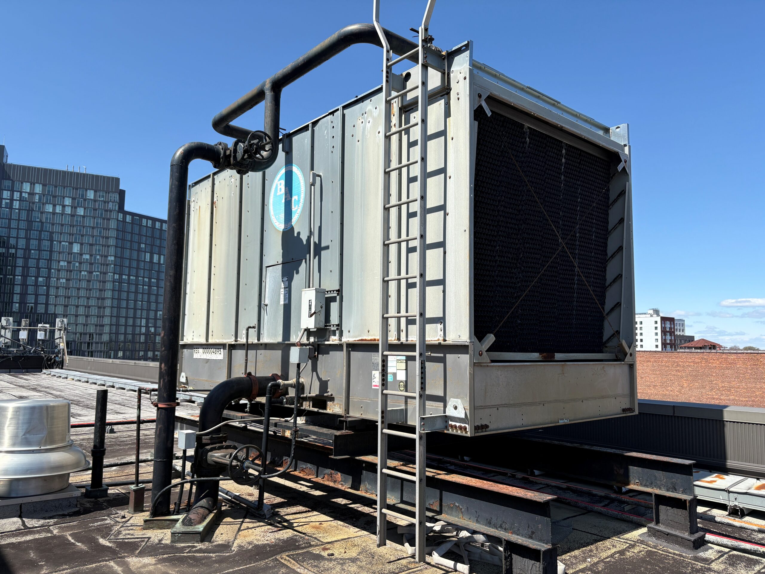
The existing open cooling tower is in poor condition and has reached the end of its service life. The new system requires that system water not be exposed to outside air; accordingly, the existing open tower will need to be replaced with a closed tower (see Figure 1).
The chiller heater system, located outside, will be exposed to freezing temperatures during its year-round operation. Propylene glycol must be added to the system water, creating a condenser water solution that will not freeze. While ethylene glycol is also an option, propylene glycol is usually preferred because it is less toxic and easier to handle. Ethylene glycol may be used in climates with lower temperatures, yet in many climates, including New York’s, propylene glycol is a standard choice. The new system design requires a closed tower to maintain the proper condition of the glycol-water solution.
The water-cooled condensers of the new heat pump units reject heat into the water flowing in the condenser water pipes. This water then rejects heat to the outside air through the new closed cooling tower. The water flowing from the units to the cooling tower is circulated through a coil inside the cooling tower. The cooling tower water is discharged from the pipe at the top of the cooling tower and sprayed over the coil. The water passing over the coil rejects heat to the air drawn over the coil by the cooling tower fan. The cooling tower collects water in the basin sump where it is drawn into a pipe and then returned to the discharge opening at the top and the process repeats. The sump basin of the cooling tower contains an electric resistance heating coil to prevent the water from freezing during low outdoor temperatures.
The support steel of the existing tower is corroded and requires replacement for the installation of the new tower. The new support steel requires collaborative design between a structural engineer and an architect. The structural engineer will design the new support steel and connections to the existing building frame, while the architect will design a new roofing system and waterproofing around the new steel connections. This is a similar process to the new steel required by the new chiller.
In some instances, existing support steel may be reused, however, mechanical engineers must never assume that is the case. Proper inspection of the steel by structural engineers is required, even when the support appears to be in good condition as corrosion or other conditions necessitating replacement can be hidden by something as simple as paint, for example.
Replacement of air conditioners with heat pumps
Based on modeling, heat pumps are selected to replace floor-mounted vertical configuration air conditioner units. The heat pumps are similar-sized vertical configuration units that are to be installed in place of the air conditioners and connected to the ductwork and piping systems. The ductwork and piping will be repaired as needed for reuse in the new system.
Vertical water-cooled heat pumps may replace existing water-cooled air conditioners. The new heat pumps have a similar size and airflow to the existing air conditioners. Therefore, the new heat pumps may be installed in the same mechanical rooms and in a similar configuration to existing units.
The design also includes replacing sections of ductwork and piping that are in poor condition. Fortunately, most of the ductwork and piping can be reused in the new system, providing considerable savings and making this option the most cost-effective solution.
The duct heaters are to be removed from the ductwork, as the new heat pump units will include an electric resistance heater to supplement the heat pump operation. This resistance heat is intended only as a backup, since the heat pump capacity is calculated to fully meet the heating needs of the building.
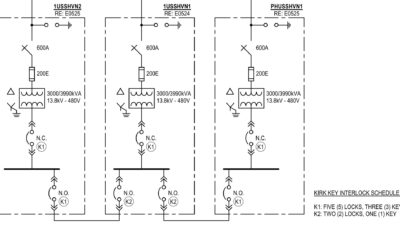
Electrical systems and connections
Electrical modifications to the existing electrical service are a critical design requirement. The existing electrical service was observed to confirm that the connection to the new chiller is feasible. The utility provider must receive a load letter to confirm that the new loads are permissible for the building’s service connection.
The new heat pumps that replace the air conditioners require a similar electrical power connection. The chiller power connection is a new connection and therefore will require a new feeder from the existing electrical service to the chiller.
Operation and performance
The modeled system heats the building in the winter months using the chiller heater and interior airside heat pumps connected to the space’s distribution ductwork.
The refrigerant cycle of the chiller heat pump uses the evaporator to extract heat from the outside air into the refrigerant, which absorbs the heat. The heat from the refrigerant is released into the system water, after which the compressor increases the temperature and pressure of the refrigerant. The refrigerant then passes through an expansion valve and is returned to the evaporator to repeat the process.
The interior airside heat pumps draw the heat from the water using the refrigerant cycle to heat the air of the occupied space.
The system cools the building in the summer months using the cooling tower and interior airside heat pumps connected to the space’s distribution ductwork.
The interior airside heat pumps draw heat from the indoor air and reject it to the water using the refrigerant cycle to cool the space. The system water is circulated through the cooling tower, which rejects heat to the outside air and cools the water without a refrigeration cycle.
Coincidental heating and cooling operation
The system operation maintains the water temperature within the operating range of the interior heat pumps. Interior heat pumps draw or reject heat to the system water as needed for heating or cooling operation. This configuration allows each heat pump to heat or cool each space according to the setpoint temperature of that zone’s thermostat.
Electrification in this design resulted in lower overall energy costs and reduced electrical power consumption. The primary contributors to this energy reduction included the replacement of deteriorating windows and the elimination of the resistance electrical heat, which supplements the gas heating. Electrification also achieves a lower carbon footprint, with the potential for further reductions as the electric grid continues to decarbonize.
Electrification in this region often requires a larger electrical service, however this project demonstrates that such increases are not always necessary.
While the combination of new windows and a new gas-fired heating plant would yield lower energy costs under current utility prices compared to full electrification, this approach would not achieve building decarbonization.