While campus chilled water loops using water-cooled chillers and cooling towers are almost always more energy efficient than similar distributed systems, there are scenarios where it may behoove building operators to detach from those systems.
Learning objectives
- Discuss the general benefits of campus loop chilled water systems such as energy efficiency, redundancy and maintenance.
- Understand some of the factors that may drive building operators to opt for stand-alone systems based on building typologies and facility-specific demands.
- Review a site-specific case study at the Medical College of Wisconsin, as well as anticipated energy and cost savings from a unique, stand-alone heat recovery chiller system serving process cooling end-uses.
Chilled water insights
- Campus and district energy systems centralize heating and cooling production — often generating chilled water, steam and hot water — to serve many buildings more efficiently, reducing energy use, emissions and maintenance costs while improving reliability.
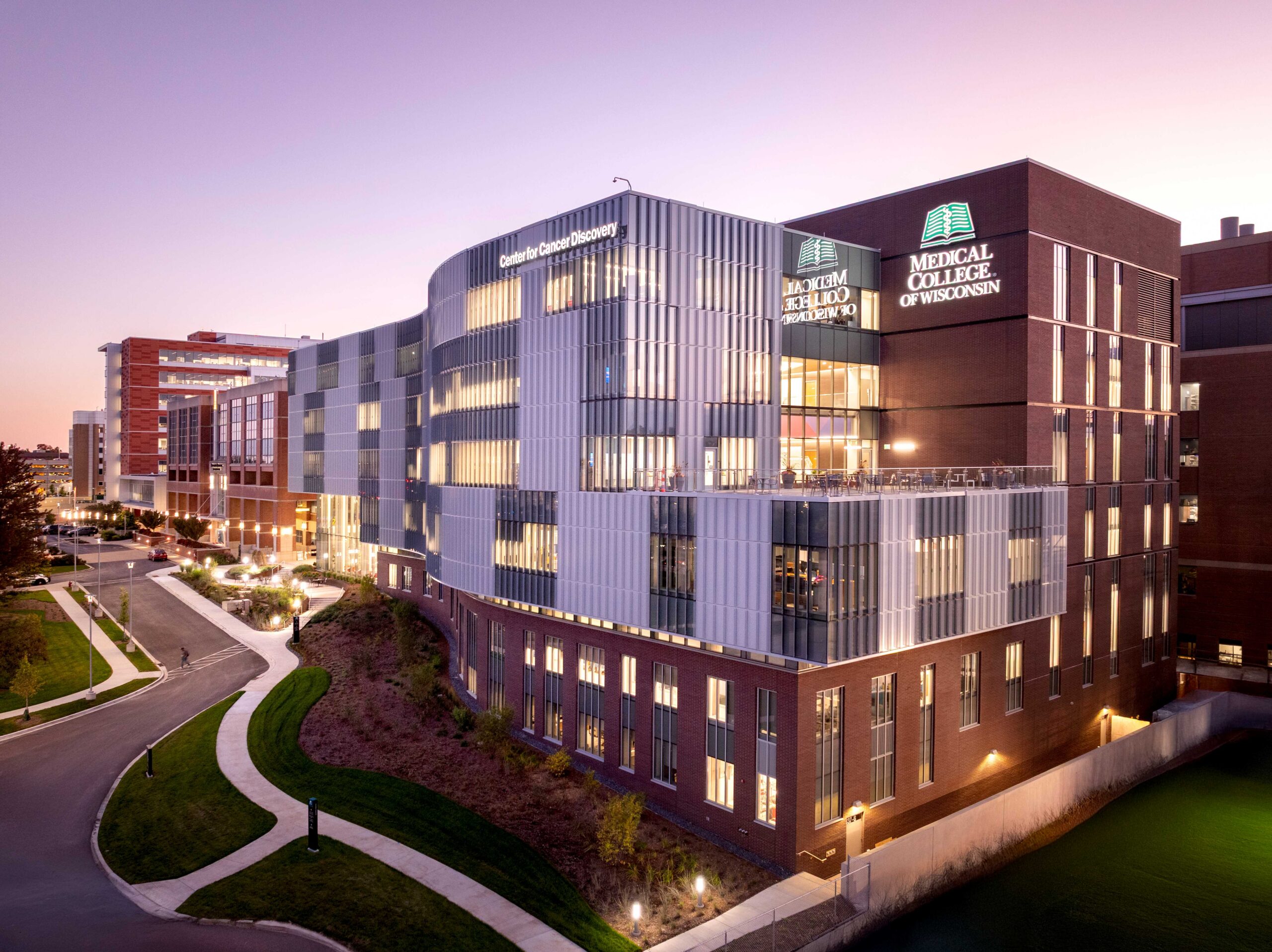
- At the Milwaukee Regional Medical Center campus, a large thermal plant distributes chilled water and steam to more than 25 buildings, while the Medical College of Wisconsin’s Center for Cancer Discovery supplements this supply with a specialized heat recovery chiller system to meet precise year-round cooling needs and recover waste heat for building heating.
Campus or district heating and cooling systems are large-scale plants, generating chilled water, hot water or steam — or some combination of all three. They provide these utilities on varying scales from small loops serving a few buildings all the way to large districts with multiple plants providing heating and cooling to hundreds of buildings and millions of square feet (such as the CenTrio system in Chicago).
By centralizing generation of heating and cooling, these systems can achieve greater efficiency than distributed building-level systems, reducing energy consumption and greenhouse gas emissions while improving resilience, leveraging economies of scale to minimize initial investment costs of redundant systems. These systems can also improve reliability and reduce peak demands by employing energy storage systems.
For building owners, connecting to a district system often lowers maintenance costs, extends equipment life cycles and frees up valuable space that would otherwise be used for mechanical equipment.
One such example is the Milwaukee Regional Medical Center (MRMC) thermal plant in Wauwatosa, Wisconsin. Located 7 miles west of downtown Milwaukee, MRMC is a consortium of four major health care institutions on a single campus: the Medical College of Wisconsin (MCW) Children’s Wisconsin, Froedtert Hospital, Versiti Blood Research Institute.
The thermal plant (referred to as MRMCT for short) is operated, maintained and managed by Ever-Green Energy and serves more than 25 buildings over 7 million square feet on the campus. Providing chilled water and both low (15 pounds per square inch gauge [psig], nominal) and high (135 psig, nominal) pressure steam services to the buildings from three main plants:
- Twelve chillers with 23,000 tons of cooling capacity.
- Five boilers providing nearly 350,000 pounds/hour of steam.
- Two pressure-reducing valves, reducing 140 psig steam from the boilers to 17-20 psig for low-pressure distribution.
- Bidirectional services for both chilled water and steam utilities, providing service reliability exceeding 99.999% to users.
- Multiple plant and controls upgrades in the past 10 years, allowing for plant efficiencies (as of 2025) of 70.9% thermal efficiency for heating and a cooling coefficient of performance of 4.83.
- Reported 70% reduction in greenhouse gas emissions from 2013 to 2020.
- Contractually guaranteed chilled water temperatures:
- 42°F when outside air > 50.5°F
- 48°F to 50°F when outside air < 49.5°F
- Reliable, year-round pricing with moderate year-over-year increases, with consumption rates as follows:
- Chilled water ($/ton-hour): $0.1799 (2025), $0.1870 (2026, expected)
- Steam ($/1,000lb): $7.18 (2025), $7.47 (2026, expected)
- No rate difference in low- versus high-pressure steam usage.
MCW CCD building systems
While this plant configuration provides reliable and affordable utilities to the buildings on campus, some building functions may not allow operators to rely solely upon the district system as readily as others. The MCW Center for Cancer Discovery (CCD)is a prime example. Completed in summer 2025, key project team members included: CannonDesign (Architect and Engineer), Mortenson Construction (Construction Manager), JM Brennan (Mechanical Contractor), Staff Electric (Electrical Contractor) and The Concord Group (Owner’s Representative).
This building provides 155,000 square feet of both office (45%) and laboratory spaces (55%) for researchers and administrative staff across six floors. A single, 70,000 cubic feet per minute (cfm) variable air volume (VAV) air handling unit (AHU) serves the office spaces, while twin 50,000 cfm dedicated outside air systems (DOAS) are headered together to serve the multitude of laboratory space typologies, including: a bio-hub and incubator lab, metabolomics, tissue culture, cellular microscopy, necropsy, molecular biology, life-science and biological labs and nearly 20,000 square feet of general purpose lab bench space. A fourth custom VAV AHU is being installed to serve a 5,000-square-foot cell therapy suite currently under construction.
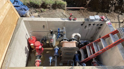
Cooling at the AHUs is provided by chilled water from the MRMCT plant via a direct connection (no heat exchanger), using the distribution pumps at the plant, though a chilled water pump in a side-stream configuration is available should the plant pumps not provide adequate pressure to deliver the required chilled water flow.
The building uses two distinct heating loops: one for AHU preheat using a 45% propylene glycol (PPG) mix and one for reheat coils and perimeter heating (water-only). Both loops use plant steam as the primary heat source via two redundant shell-and-tube heat exchangers per loop. While the preheat loop only requires two pumps for distribution and steam control valves for loop temperature control to serve the building AHUs, the combined reheat and perimeter loop is more complex.
Like the preheat loop, steam control valves provide temperature control of the common (source) loop, while four separate sub-loops — one reheat and three perimeter heating loops (one per major exposure, no major south-facing exposures) — use three-way valves to mix sub-loop return water with source supply water for precise temperature control while a dedicated loop pump provides distribution to each loop.
While most of the building’s heating and cooling needs are met by the MRMCT plant, sole reliance on the plant did not make sense for more critical process cooling loads. Early in the design process, the design team and MCW worked closely together to solve three key design problems which ultimately informed the decision to decouple these loads from the MRMCT plant system. While the CCD is not the only building in the MCW portfolio to decouple part of its cooling systems from the plant, the reasons to decouple are as unique as the building itself.
Challenge No. 1: Support precision-cooled spaces
To properly support the research mission of the facility, the CCD building has three walk-in coolers with water-cooled condensing units and 13 dedicated rooms designated for cold-storage or freezer farms — all of which require year-round cooling. In addition to these specialty spaces, mechanical, electrical, telecom and elevator equipment rooms (spaces common to nearly all building types) require cooling to support the CCD as well.
Though providing higher chilled water temperatures (48°F to 50°F) at outdoor dry bulb temperatures below 49.5°F allows the MRMCT plant to operate more efficiently by taking advantage of lower cooling tower approach temperatures and water-side economizer controls, the higher temperatures are not conducive to the precise temperature and humidity control ranges required by some of the lab support equipment.
Challenge No. 2: Energy recovery necessity
The DOAS systems serving the lab spaces are not required by code (Wisconsin referenced International Energy Conservation Code 2009 edition at the time of design) to use energy recovery by Exception 2.1 of Section 503.2.6, which states that energy recovery systems are not required for laboratory fume hood systems with “VAV hood exhaust and room supply systems capable of reducing exhaust and makeup air volume to 50% or less of design values.”
While code may not require the use of energy recovery, the owner’s own sustainability goals and economic analysis concluded that with 100,000 cfm of air to condition, the payback for almost any type of system would justify initial investments well within the life cycle of the building.
Challenge No. 3: Airflow rates
Per Table 403.3.1.1 of the International Mechanical Code (2021 edition), science laboratories are required to provide 430 cfm of fresh air per 1,000 square feet (assuming the listed occupant density of 25 people per 1,000 square feet) of lab space.
Additionally and a key driver for these spaces, is that the table also requires 1 cfm per square foot of exhaust air, which may not be recirculated at a rate of more than 10% of the total supply volume to the space, per footnote “g” of Table 403.3.1.1. While this threshold still permits the usage of enthalpy wheels and other energy recovery technologies (which inherently have a small amount of leakage or crossover between the exhaust and supply air streams), the potential risks to occupant safety, particularly in laboratory and research buildings, cannot be understated.
Out of an abundance of caution, the facilities and the environmental health and safety teams at MCW collaborated to mandate two key design requirements at the CCD building:
- Restrict the use of energy recovery systems with any risk of leakage or crossover between the two airstreams.
- Provide airflow rates beyond code minimums, requiring a minimum of eight air changes per hour to all lab spaces during occupied periods. While providing more airflow than is needed to meet cooling loads can provide a safer environment for occupants, it requires significant reheat energy to not over-cool the space when that minimum airflow rate exceeds what is required to meet envelope and internal heat gains.
Process cooling solution via chilled water, heat recovery
The challenge of providing reliable year-round cooling with tight temperature control is easy enough to solve on its own by providing a small chiller plant (either air-cooled chiller or water cooled with cooling tower, depending on required cooling load).
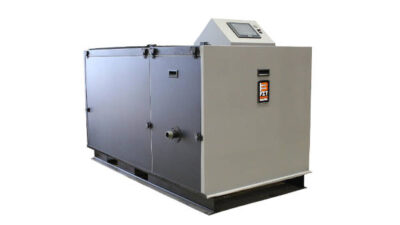
However, the need to recover energy at the laboratory DOAS units combined with year-round reheat demands drove the team to implement a modular dedicated heat recovery chiller system. Using five (20-ton, nominal) dedicated heat recovery chillers, the configuration of the condenser water loop truly sets this system apart from others of its type. The chiller provides 42°F process chilled water to the cooling end uses, while the condenser water loop operates on a 100°F to 120°F delta T.
While other heat recovery chiller systems almost always still rely on a cooling tower as means to reject heat when no other path is available, the system at the CCD uses no cooling tower at all, instead using a stepped approach to its heat rejection strategy.
There are two available paths to reject heat from the condenser water loop (see Figure 2). Path 1 (red) uses a modulating three-way valve in a diverting configuration to first reject heat to the building’s combined reheat and perimeter (fin tube) heating loop, modulating the valve position to divert water toward port 2 as required to maintain the condenser water supply setpoint at TS3 (green).
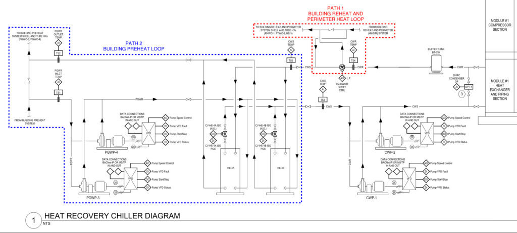
This connection sends the warmest water directly to the inlet of the reheat and perimeter loop heat exchangers, while the coolest water from the reheat and perimeter loop mixes into the condenser water loop, achieving two important goals: Condenser water to the chiller inlet is cooled, while reheat loop water to the heat exchanger inlets is warmed, thereby reducing purchased steam consumption.
During periods when the available condenser heat exceeds the demand of the reheat and perimeter loop (i.e., when the three-way valve is diverting 100% of condenser water flow and TS3 setpoint is not met), path 2 (the building preheat loop) provides a means to reject the remainder of the heat. Plate and frame heat exchangers provide a physical barrier between the condenser water loop (pure water, no glycol) and the preheat loop (45% PPG).
This connection to the preheat loop is hydraulically separated from the rest of the loop similar to a primary-secondary arrangement on a boiler or chiller plant, allowing the pumps (PGWP-3,4) dedicated to the heat exchangers vary their speed as required to meet the condenser water setpoint at TS3 without affecting the normal operation of the preheat loop (see Figure 3). In the same way as path 1, the coolest water from the preheat loop is diverted through the heat exchangers, providing the rest of the required heat rejection for the chiller’s condensers, while also pre-heating the return water to the preheat loop heat exchangers and reducing purchased steam consumption.
The multipurpose preheat loop
Though many heat recovery chiller systems may have multiple heat sinks to which heat can be rejected, what makes the system at the CCD truly stand out is the valving arrangement at the DOAS units preheat and exhaust air coils.
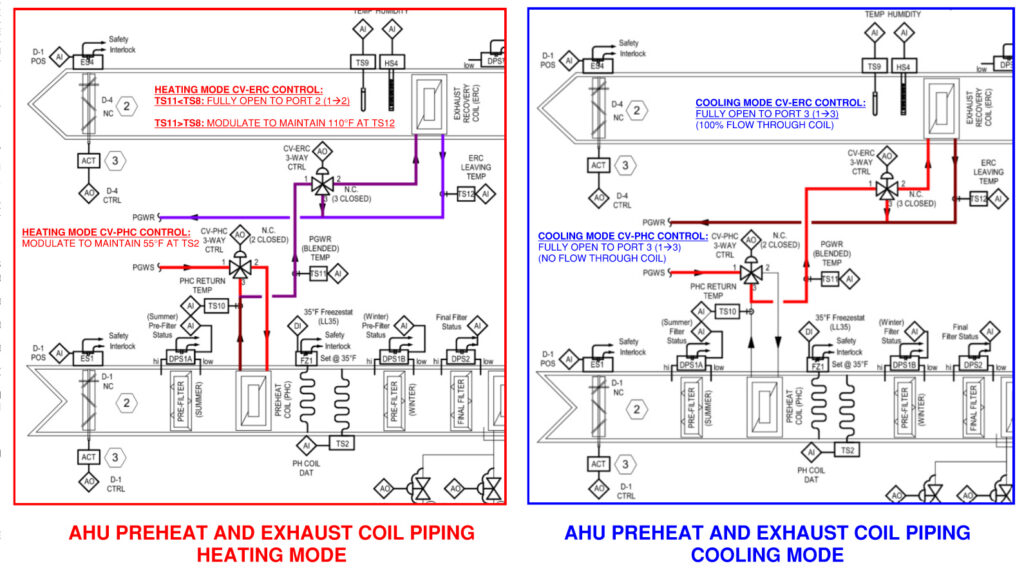
The preheat loop water can serve multiple functions depending on DOAS mode (heating versus cooling):
- Heating mode:
- CV-PHC modulates open to port 2 as required to meet the DOAS unit leaving air setpoint (55°F) in heating mode. From there, return fluid from the preheat coil is mixed with any fluid through Port 3 and flows to CV-ERC.
- When the exhaust air entering the coil is warmer than the blended fluid temperature at TS1, CV-ERC modulates fully open to recover as much exhaust air heat as possible to preheat return fluid to the steam-source heat exchangers.
- When exhaust air is cooler than the blended fluid temperature at TS11, CV-ERC modulates as required to maintain a 110°F temperature setpoint at the common inlet of PGWP-3 and PGWP-4, eventually acting as the supply fluid to the DOAS preheat coils. Multiple combinations of entering preheat coil temperatures and chiller condenser water return temperatures were evaluated and despite the low preheat coil temperature, the resulting four-row coil minimized DOAS air and water pressure drops while keeping chiller efficiency at a reasonable value.
- Cooling mode:
- CV-PHC modulates fully open to port 3 (port 2 fully closed) allowing the fluid to bypass the preheat coil during summer and not needlessly adding more load for the cooling coil.
- CV-ERC modulates fully open to port 2, flowing all fluid through the exhaust coil and rejecting as much heat as possible to the exhaust stream.
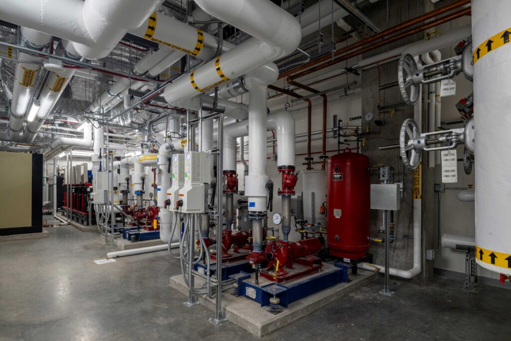
Most of the system components, including chiller, condenser water pumps, plate and frame heat exchangers and preheat glycol water pumps are shown in Figure 4.
Calculating recovered energy and costs
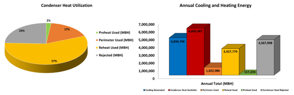
The performance of the heat recovery chiller system was modeled over the course of a full year in the Milwaukee climate using 8,760-hour weather data from Milwaukee Mitchell International Airport to accurately predict all key performance aspects of the system, including: cooling generated, condenser heat available, reheat + perimeter heat used, preheat used and condenser heat rejected.
The results largely matched expectations for nearly all data points (see Figure 5):
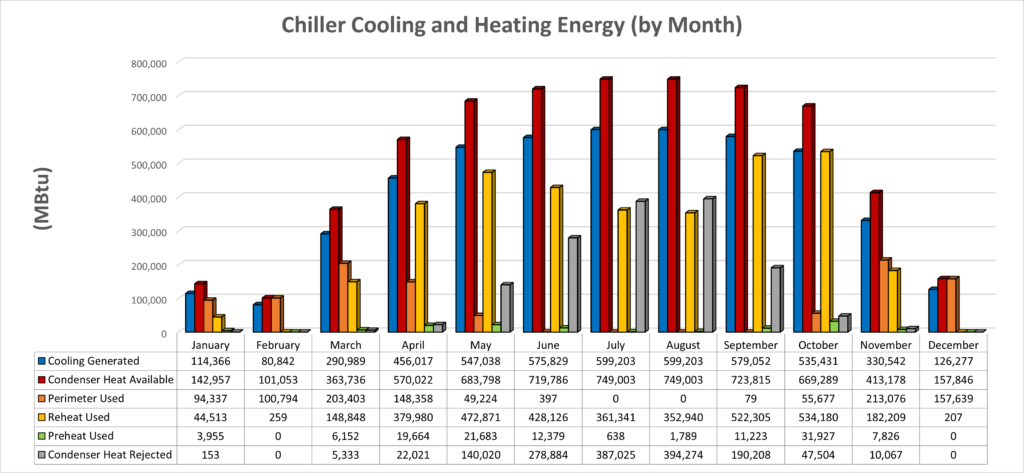
- Cooling generated was minimal during the winter months (November through February) and gradually began to peak into the warmest summer months of July and August. As condenser heat is only available when cooling is being generated, the amount of heat available for recovery is the amount of cooling generated multiplied by the condenser heat of rejection ratio of 1.25. For example, when 100 MBtu of cooling is generated, 125 MBtu of heat is available for recovery from the condenser loop.
- As it is the first available path of condenser heat rejection, the combined reheat and perimeter loop used most of the annual available heat for recovery, nearly 75% (see Figure 6):
- While the perimeter (fin tube) loop accounted for only 23% of the recovered heat use in the combined loop, its use occurred only from October to May, peaking in the coldest months as expected.
- Conversely, the reheat usage was minimized in the coldest months as available heat was being used for the perimeter loop while it began to increase in the summer months when perimeter loop demand for heat began to reduce.
- As the 45% PPG building preheat loop only recovers heat when the combined loop cannot dissipate 100% of the condenser heat, the amount of heat used by the preheat loop all but disappears, only accounting for 2% of annual recovered heat.
- Despite the minimal reduction of steam consumption by the preheat loop, this loop connection cannot be eliminated. Approximately 25% of the condenser heat generated annually must still be rejected, particularly during the summer months of May through September (see Figure 5).
Overall, the system achieves remarkable results, recovering more than 75% of all available waste heat generated from process cooling demands every year.
However, energy savings alone cannot justify the implementation of systems like this to an institution like MCW — the system must make financial sense as well. With an installed system cost of $870,000 (chillers, process chilled and condenser water piping, pumps, heat exchangers and hydronic specialties), the system must achieve significant financial savings to achieve a reasonable payback period.
Using the modeled results and projected 2026 utility rates, annual savings and operating costs for the system are expected to be:
- Offset purchased utility costs:
- Chilled water: 402,899 ton-hours at $0.1870/ton-hour: $75,342 per year
- Steam: 4,758,331 pounds/year at $7.47/1,000 pounds: $35,545 per year
- Annual operating costs:
- Electrical consumption only (no demand): 690,616 kilowatt hours (kWh): $50,548
- On peak (6 a.m. to 6 p.m.) rate: $0.08968/kWh
- Off peak (6 p.m. to 6 a.m.) rate: %0.05511/kWh
- Maintenance costs: $8,000/year
- Electrical consumption only (no demand): 690,616 kilowatt hours (kWh): $50,548
At a net savings of $52,340 per year, the initial system investment of $870,000 pays back (simple payback) in 16.6 years, well within the expected lifespan of this facility.
Evolving heat recovery system design
Like many of the most innovative heating, ventilation and air conditioning systems in the industry, this heat recovery strategy has evolved through multiple iterations and ongoing optimizations. This system started (in a different MCW building) as a water-to-water heat pump system whose condenser loop was connected to the campus chilled water system, but improving technologies and ongoing optimization efforts ultimately led to the current approach of using the building’s heating systems as a heat dump.
The CCD project was the first project for MCW where this system was fully captured in design documents with a fully defined sequence of operations.