Several types of chillers, along with various pumping configurations, provide flexible and efficient solutions for cooling needs.
- Identify different types of chillers and their building applications.
- Understand the components and working principles of chillers.
- Evaluate the benefits and drawbacks of various chiller system arrangements.
Chiller insights
- Chillers use the refrigeration cycle to remove heat from water or other fluids, with the extracted heat either dissipated into the environment or repurposed for heating applications.
- Various chiller types and system configurations, including air-cooled and water-cooled options, different compressor technologies and single or multiple-chiller arrangements, impact efficiency, operational flexibility and energy consumption in commercial and industrial settings.
Chillers remove heat from water (or other liquids, such as a glycol mixture) by using the refrigeration cycle. The removed heat is either rejected from the chiller into the environment or it can be beneficially used for heating the building or an industrial process.
This resultant cooled water is then used to remove heat from buildings and industrial processes. The cooled water is pumped through a closed system of pipes to the cooling load and then returned to the chillers to be cooled again.
A basic chiller consists of a compressor, evaporator, condenser and an expansion or flow control device. Specialized chillers, referred to as heat pumps, can reverse the process to provide either heating or cooling as required or even both simultaneously.
Chiller types
Chillers vary in terms of methods of heat rejection, types of compressors, heat exchanger types and arrangement of these components. Removed heat can be rejected into air, water or other fluids. Air-cooled chillers use air to remove heat from the refrigerant at the condenser, while water-cooled chillers use circulating liquid.
In most cases, air-cooled chillers need to reject their heat into outdoor air. Therefore, the entire unit must either be split with the condenser located outside and the compressor located inside or be packaged in a single unit located outside. Alternatively, the heated condenser air can be ducted outdoors. The temperature to which the condenser can be cooled is limited to the dry bulb temperature of the ambient air and air has a lower heat transfer coefficient than water. This makes air-cooled chillers less energy efficient than water-cooled chillers.
For these reasons, air-cooled chillers are typically only used for smaller scale systems; the exception is an area with limited water resources. Water-cooled chillers are more common for medium to large plants because they are available in larger capacities, which means they can provide higher cooling capacities with less units than air-cooled chillers and can also use lower energy per ton of cooling.
Water-cooled chillers commonly use cooling towers to reject heat. Cooling towers cool water via evaporation. The cooling tower water temperature is limited by the wet bulb temperature of the ambient air.
However, cooling towers add a level of complexity above air cooled chillers because of the added components and requirements for handling the water with additional pumps, piping, water chemistry, biological growth and disposal of the blowdown water. The factors described above require careful consideration to select the system with the best life cycle costs.
For small systems from a few tons up to a few hundred tons are usually air-cooled. Systems greater than several hundred tons into the tens of thousands of tons are usually water-cooled. The factors that need to be weighed for medium sized system in the 100- to 500-ton range are first system capital costs, energy costs, operator availability and knowledge, annual operating hours requiring cooling, availability of free cooling economizer hours.
Water and sewer costs and other environmental factors may include water and waste reduction goals, greenhouse gas emissions, noise pollution and refrigerant usage.
Other factors also include system physical size. Shipping limitations determine package sizes. Site limitations are also a factor. Air-cooled chiller packages are usually located outdoors, often on a rooftop or on the ground near the cooling load. At least in freezing climates, water cooled chillers are in a building or a mechanical room
Other cooling sources are natural water bodies, such as lakes, rivers and oceans. The ground is also an available heat sink in the case of geothermal systems. Using only the ground as a heat sink is not recommended because the increase in temperature over the years will render the ground unusable once the practical temperatures are exceeded. The stored heat from summertime cooling can beneficially be used as a heat source in the winter. If the system is heating-dominant, too much heat will be removed from the ground and the ground temperature will drop over time. The opposite is true for cooling-dominant systems — when the annual loads are balanced the conditions are ideal for a geothermal system.
Compressor types
Chillers can use several types of compressors — scroll, reciprocating, centrifugal and screw. Except for reciprocating compressors, these are commonly used in different chiller applications. Over time, innovations to improve the efficiency, reliability and controllability of centrifugal, screw and scroll compressors have reduced the use of reciprocating compressors.
The distinguishing characteristic of scroll and reciprocating compressors is that when pressure rises, their capacity is impacted significantly because these compressors operate in discrete steps or even cycled on and off, rather than continuously. This stepped reduction in capacity contrasts with centrifugal and screw compressors, which use continuous modulation for capacity reduction. For instance, in a scenario where precise temperature control is needed, centrifugal compressors can continuously adjust their capacity to match varying load conditions efficiently.
Scroll and reciprocating liquid chillers are well-suited for use with air-cooled condensers because pressure rise has a minor impact on the volume flow rate of the compressor, thus allowing scroll and reciprocating liquid chillers to retain almost full cooling capacity even when the wet bulb temperature is above the design parameter. Air-cooled scroll and reciprocating liquid chillers can be equipped with a reversing valve in the refrigerant circuit — this allows them to be applied as heat pump chillers and to be configured seasonally for heating or cooling. Centrifugal compressors are ideal for energy conservation and precise temperature control because they can continuously adjust their capacity within a limited range of pressure ratios to effectively match various load conditions with proportional power consumption changes.
Like scroll and reciprocating compressors, screw compressors are positive displacement machines. Screw compressors have a high maximum working pressure, continuous lubricant scavenging, no flood coolers and are designed for high turndown ratios. These factors allow them to have the least capacity reduction at high condensing temperatures.
Chillers may also include a receiver, economizer, expansion turbine, sub-cooler and other auxiliary components.
- Receivers store liquid refrigerant as the ratio of vapor and liquid vary depending on cooling loads.
- Economizing process can occur in a direct expansion of a flash system.
- Expansion turbines remove rotating energy while a portion of refrigerant vaporizes.
- Sub-cooling occurs when condensed refrigerant is cooled below its saturating condensing temperature. Sub-cooling reduces the necessary amount of liquid refrigerant that flashes in the evaporator to bring the liquid refrigerant temperature down to the saturation temperature at the lower evaporator pressure. Any refrigerant that flashes reduces both the system efficiency and capacity. Sub-cooling can happen in the sub-cooler section of a water-cooled condenser or in a separate heat exchanger.
- Liquid injection can reduce noise in centrifugal compressors and can also be used for lubricant cooling in screw compressors (when injected into a port slightly below discharge pressure).
Chiller system arrangement
Chillers can be used in single- or multiple-chiller arrangements. When designing a system, it is important to consider the costs and benefits of each arrangement.
A basic single-chiller configuration with one compressor is a simple and compact system making it a popular choice for chilling water for air conditioning in a small single building.
A more complex multiple-chiller system can allow for operational flexibility and standby capacity, making maintenance less disruptive. Using multiple smaller chillers can reduce the power costs during partial load conditions. However, using multiple chillers may cause an increase in installation costs and space requirements.
Multiple-chiller systems can be arranged in parallel or series arrangements.
In a parallel arrangement, there are two primary features:
- The chillers are independently cooling the liquid.
- All units are controlled by a combined exit liquid temperature and the chilled water temperature can be used to cycle units on and off to adjust capacity to maintain chilled water temperature.
Each chiller’s load is proportional to its flow at any given delta T. Parallel arrangement can allow for more flexibility in load distribution, particularly for larger loads. Figure 3 depicts a parallel chiller arrangement
In a series arrangement, the liquid flows through each chiller in the series, independently reducing the temperature proportional to its share of the load (in low system loads, one chiller may be able to handle the entire temperature reduction). Series chillers are useful if there is a high system differential temperature because each chiller can be optimized to operate with a more defined entering and leaving water temperature.
The high differential temperature indicates that the system flow is reduced; however, the pressure drop is additive for the chillers in series (i.e., the pressure drop of each individual chiller in the series is added together to calculate the total pressure drop). Series arrangement can be more efficient at lower loads because it is more energy efficient at partial load conditions. Figure 2 shows a series chiller arrangement.
Chilled water distribution systems
Chiller systems can have constant or variable flow. Traditionally, constant chilled water flow has been applied to smaller systems with straightforward design and operation and low distribution costs. Constant flow can be applied to primary, secondary and tertiary systems. Primary flow pumps need to be designed to overcome the pressure loss of the sub loop with the greatest pressure loss.
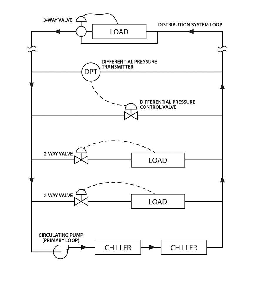
Because the flow of these systems is constant, capacity can only be changed via the system differential temperature. Decreasing differential temperature subsequently decreases system efficiency. Understanding the basics of a constant-flow system is fundamental to understanding the intricacies of the more complex distribution schemes (see Figure 2).
Modern systems need variable-flow pumping to meet the energy efficiency requirements prescribed in ASHRAE Standard 90.1: Energy Standard for Buildings Except Low-Rise Residential Buildings. New control systems mitigate the need for constant flow through chillers and improve upon many of the issues found in large constant-flow systems.
Variable-flow design can reduce energy use and expand the capacity of the distribution system through diversity. Multiple variable speed pumps can reduce flow and pressure, thereby lowering pumping energy during partial load conditions. Variable-flow requires that terminal device controls be installed to ensure flow conditions are met. By using correctly sized two-way valves and pressure-independent control valves (PICV), the continuous high-return temperature — needed to correlate the system load change to a flow change — can be provided.
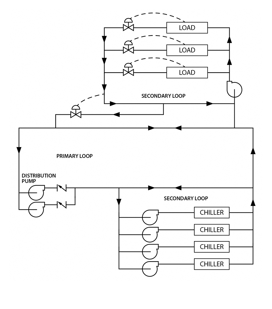
Pumps can be arranged in several ways based on system size and distribution. Primary/secondary pumping is common. In this setup, a primary loop in a central plant handles overall circulation, while secondary loops connect loads and chillers, decoupled from the primary loop. Primary pumps move large volumes at low pressure, while secondary loops are tailored to specific needs. Each load has a pump sized for its pressure loss, thus preventing one subsystem from dictating others’ operating points (see Figure 3).
Larger primary loops can cause downstream temperature increases if multiple secondary loops increase the temperature of the chilled water as it is added back into the primary loop. Each subsequent downstream secondary loop then receives warmer supply temperatures than the upstream loops. Consequently, this affects the performance of the downstream loops. Intermediate chillers can mitigate this issue. However, this configuration is not suitable for single central plant system
In medium-sized systems, primary pumps provide flow through chillers and the primary loop. Tertiary systems with in-building pumps are useful for retrofits where existing building systems are served by a new central plant. Tertiary systems also work within buildings with varying loads, such as heating, ventilation and air conditioning (HVAC) and process loads.
For exceptionally large systems, distributed pumping can be used where pumps are distributed to various buildings and sized only for pressure loss in a particular building. With distributed pumping, the need for distribution pumps within the central plant is eliminated; rather, the pumps are in their respective buildings. This allows the distributed pumps to be sized for the pressure loss in a particular location instead of the significant pressure loss required by large distribution network piping.
Distributed pumping is ideal for new construction where the distributed buildings and central plant can be fully planned and coordinated, as opposed to system that may require new loads to be added in the future (significantly affecting the pressure drop of each distribution pump).
Delta T syndrome
Ideally, a chilled water system should operate at a constant temperature difference. Chilled water supply temperature can be varied as a function of dehumidification demand, but the return temperature should vary accordingly.
A frequent problem with chilled water systems is that when the system load decreases the chilled water temperature also decreases, thereby coming closer to the supply temperature. This phenomenon is known as “low delta T syndrome” and essentially means that flow does not decrease as desired and therefore negatively impacts both pumping energy and chiller efficiency.
This problem can be eliminated or reduced by controlling secondary load loops and including pressure-independent control valves. The secondary loop should be adjusted to prevent over-pumping of water and pressure-independent valves should be adjusted to maintain a constant pressure to the control valve (to compensate for variations in system pressure at varying flow rates). An advanced version of a pressure-independent valve is known as an energy valve. With built-in onboard flow and delta T measurement, these valves actively control the delta T of each coil.
As an added benefit, data logging is available to record the valve performance and energy usage of each coil. These data are useful for energy monitoring and system troubleshooting.
Selecting a chiller and design guidelines
Energy usage is a major consideration when designing any system. Distribution systems offer a few ways to save energy and energy costs, such as:
- Using variable speed pumping to save energy.
- Using a practical lower limit of 39°F (because temperatures below that can lead to increased and unnecessary energy usage).
The exception to this is where lower chilled water temperatures are required to provide increased dehumidification or other process requirements. With low chilled water temperatures, the chiller manufacturer should be consulted as glycol may need to be added to the water to prevent freezing in the evaporator heat exchange surfaces. The addition of glycol will add operating costs to the system.
Refrigerant choice is a continually evolving challenge, with several issues to consider. The environmental impact is the primary factor influencing the latest selection of available refrigerants. International efforts aim to reduce greenhouse gas emissions, favoring refrigerants with lower global warming potential (GWP). Regulations are steering the industry toward lower GWP alternatives. GWP evaluates the overall impact on global warming, considering both the effects of refrigerant chemistry and the energy required to operate the system.
Different applications have unique cooling demands and technical specifications. Crucial factors include temperature range and cooling capacity; ensure that the refrigerant meets operational temperature requirements.
The physical environment where the chiller will operate is another crucial consideration. Refrigerants differ in their safety classifications, which may affect installation requirements. Some refrigerants are efficient but classified as flammable, requiring adequate ventilation and safety measures. Compact or enclosed spaces may limit refrigeration options, especially those needing special handling or venting systems due to potentially high refrigerant concentrations in case of a system leak. If the chiller is installed in a confined or shared space, these factors will significantly influence refrigerant selection.
The refrigerant landscape is constantly developing, driven by stricter regulations and technological advancements. To protect the investment, it is important to anticipate future regulations and choose refrigerants that meet current standards and are likely to remain compliant as restrictions tighten. Laws regarding refrigerants vary by country. The U.S. Environmental Protection Agency regulates refrigerants under the Clean Air Act. Additionally, ambient temperature and humidity can affect the efficiency of certain refrigerants, with high ambient temperatures requiring refrigerants optimized for such conditions.
Chiller flow is another important consideration. All chiller manufacturers have a minimum and maximum allowable flow. For variable speed chillers, the low-flow limit is a function of compressor speed. The simplest method for control is to pair one pump with one chiller and allow the chiller to control its associated pump; however, in that situation, any pump or chiller that is out of service will render both components inoperable.
Compressor run time in small systems also should be considered. At low loads and low system water volumes, the temperature of the system can rapidly decrease to the setpoint, causing the compressor to shut off and the system temperature to increase rapidly. This is known as short cycling. To prevent this, the system volume should be increased by the inclusion of a buffer tank. The sizing of the tank should be done in consultation with the chiller manufacturer.
Factors such as chiller turndown, allowable cycle times and system temperature need to be factored into the tank size calculations. Four gallons of water per chiller ton (12,000 British thermal units/hour) is recommended. The added benefit of a buffer tank is more stable temperature control. If stable chilled water supply temperature is crucial, then the buffer tank size should be increased.
Chiller systems should be designed to maximize temperature differential. A 15°F temperature differential is ideal for HVAC applications. To increase efficiency at larger temperature differentials, a series arrangement should be considered to increase chiller efficiency.
Variable flow within the distribution system can be achieved with primary, primary/secondary and primary/secondary/tertiary pumping systems, which can be beneficial to large, central, chilled water distribution systems with high pressure drops. It is best practice to design a system to accommodate a low overall pressure loss and thereby decrease the complexity of a central operating system.
The types of valves used in the distribution systems play a significant role in the systems’ functionality. Two-way valves must be designed to have a pressure drop of at least 20% of the maximum design pressure drop. Industrial valves can achieve higher shutoff ratings. A PICV can provide a high continuous return temperature and change the system flow based on the system load. Owing to their pressure-independent function, PICVs will not have to modulate constantly, thus increasing longevity and energy efficiency of the valve.
Chiller codes and standards
Staying up-to-date on ever-changing industry codes and standards ensures systems are properly installed, functioning and efficient. The following standards apply:
- ASHRAE 90.1 provides minimum efficiency requirements for chillers.
- ASHRAE Standard 15: Safety Standard for Refrigeration Systems applies to handling refrigerants used in all liquid chillers and specifies the requirements for equipment rooms when the refrigerant volumes of the systems exceed threshold limits.
- AHRI Standard 550/590 provides the requirements for performance rating and testing of water-chilling and heat pump water-heating packages.
- ASME’s Boiler and Pressure Vessel Code sets the requirements for design and construction of refrigerant pressure vessels (with the exception of pressure vessels with a design working pressure less than or equal to 15 pounds per square inch gauge and water-side design and construction of condensers or evaporators with design pressure and temperature less than 300 pounds per square inch and 210°F).
- AHRI Standard 575 covers unit sound level testing methods.
Controls within the chiller
Different types of chillers need different controls.
- Modern chillers typically use a microprocessor control center to handle the control functions of the chiller, as opposed to dedicated control devices for each function. Chilled-liquid temperature sensors send either a pneumatic or electric signal to the control circuit that modulates the compressor capacity. This control is also used in chillers focused on heat recovery. A water temperature controller can unload or cycle the compressor when the cooling load drops below minimum capacity.
- Scroll and reciprocating chillers use a combination of cylinder unloading and on/off compressor cycling.
- Centrifugal liquid chillers use electric motors with speed control and pre-rotation vane modulation to reduce power consumption. A current or demand limiter is used to limit the compressor capacity to prevent current draw from exceeding design value.
- Screw compressor liquid chillers use a slide valve to adjust the compression path length. A current or demand limiter is used to limit the compressor capacity to prevent current draw from exceeding design value.
- Reciprocating chillers can use simple on/off control in small capacities, larger reciprocating compressors can unload one or more cylinders for capacity control.
Chiller design requirements
Proper design and control of chiller systems are crucial for achieving energy efficiency and reliable operation. By understanding and implementing best practices in chiller flow, load management, compressor selection and system control, chiller systems can be optimized for peak performance and sustainability.
Adherence to industry standards — such as ASHRAE, AHRI and ASME — ensures that systems are not only efficient but also safe and compliant. Modern approaches to heating and cooling can significantly reduce energy consumption and promote environmental stewardship. By staying informed about advancements in chiller technologies and control strategies, engineers and facility managers can continue to improve the efficiency and effectiveness of their cooling systems.