One does not have to be a professor of fluid dynamics to size plumbing piping; following these steps will lead to mastering this fundamental plumbing engineering skill.
Learning objectives
- Understand the basic components of domestic water service.
- Determine the design flow rate of a domestic water system.
- Calculate pressure losses in a domestic water system.
Domestic water system insights
- Accurate domestic water system pipe sizing begins with understanding applicable plumbing codes, water supply fixture units and pressure-loss calculations.
- Engineers must account for pressure-reducing valves, backflow preventers, elevation changes and equivalent pipe lengths, as each affects available pressure and system performance.
Understanding the fundamentals of sizing domestic water systems, either as a new professional or industry expert, is not simple and requires practice for proficiency. A great place to start is understanding the building codes. Outside of general industry guidelines and standards, when designing domestic water plumbing systems, specific codes adopted by a city or state will address most applicable design questions.
More than 30 U.S. states use the International Plumbing Code (IPC) published by the International Code Council to govern how plumbing systems are designed. For jurisdictions that do not adopt the IPC, engineers must adhere to the adopted code that is not the IPC for plumbing-specific design requirements.

For example, Massachusetts is a good illustration of a state-specific approach, as it does not adopt the IPC directly but instead enforces its own state-developed plumbing code, 248 CMR 10, which incorporates some national concepts while maintaining significant independent requirements and amendments. California also uses its own plumbing code, the 2025 California Plumbing Code based on the 2024 Uniform Plumbing Code.
To properly size piping for a domestic water system, it is important to know the basic components of domestic water service and how to locate the appropriate code sections to determine the proper water flow rates, which are dependent on the plumbing fixtures designed for the project. In addition to understanding flow rate and pressure requirements for certain plumbing fixtures and how to translate those to pipe sizing, it is imperative to understand pressure drop and velocity limitations within a domestic water system.
Domestic water system pressures
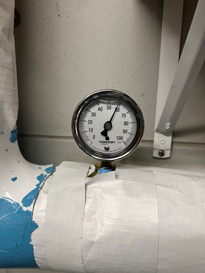
For domestic purposes, water will enter a building at a pressure typically between 40 and 80 pounds per square inch (psi) (see Figure 1). When water pressure falls below the standard 40 to 80 psi range, plumbing fixtures and appliances cannot operate properly, resulting in weak water flow, inefficient performance and difficulty completing basic tasks. At very low pressures, the system becomes unreliable, causing issues such as multifixture interference, poor hot water delivery and increased energy use due to longer appliance run times.
The maximum water pressure while water is actively flowing in a plumbing system (also known as residual pressure) allowed at any potable plumbing fixture, such as a water closet or kitchen sink, is 80 psi per the IPC. When water pressure exceeds the 80 psi limit, the plumbing system experiences continuous overstress, which accelerates wear on fixtures, appliances and piping, often leading to leaks, seal failures, burst supply lines and premature equipment breakdown. Excess pressure also causes damaging hydraulic effects like water hammer, increases the likelihood of pipe joint failure or flooding and drives higher water consumption and utility costs due to excessive flow rates.
In cities with significant elevation changes, municipal systems often supply water at pressures exceeding 80 psi to reach higher elevations, which can surpass residential design limits and increase the risk of pipe and fixture damage. As a result, installing a pressure-reducing valve (PRV) is standard practice to regulate pressure and protect building plumbing systems.
A PRV maintains safe plumbing operation by automatically adjusting a valve using a spring and diaphragm to reduce high, fluctuating incoming pressure to a steady downstream level (see Figure 2). By buffering excessively high municipal pressures to a controlled range (typically ~50 to 70 psi), it protects pipes, joints and appliances from damage and premature wear. PRVs are designed to accept low- or high-flow conditions, as applicable, and it is common practice to install a bypass valve around a PRV to minimize any water service interruptions to the building if the PRV becomes faulty.
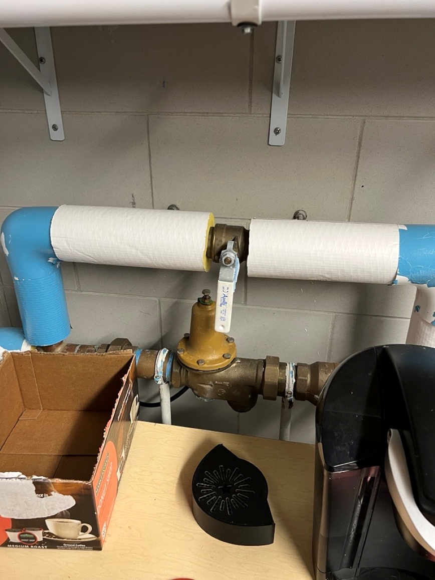
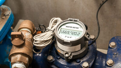
Engineers can reference Chapter 6 in the IPC for other common fixtures and requirements regarding the configuration of a water service entry. Other common fixtures installed at the water entrance of a building include backflow preventers that are part of reduced pressure zone (RPZ) assemblies, pressure gauges, valves and water meters (see Figure 3). Ball valves are common isolation valves used to shut off water flow for pipe diameters of 2 inches or less. In pipes larger than 2 inches in diameter, gate valves and butterfly valves are common for isolation, primarily due to their cost benefits.
Preventing contamination in domestic water systems
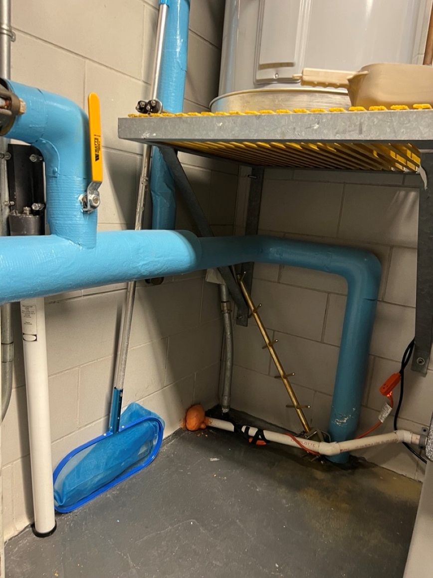
To prevent contamination from entering a municipal water supply, a backflow preventer at the building entrance is commonly required (see Figure 4). However, some utilities do not require backflow preventers for single-family homes or buildings that have no potential for cross-contamination. Other utilities require backflow prevention at the point of utility connection (e.g., immediately downstream of the water meter). In a multibuilding campus, water metering and backflow prevention may be required at the property line instead of at the building connection. For backflow preventers, it is important to determine the local cross-connection requirements. This information can typically be determined with the local utility provider or a state plumbing inspector that serves the local area.
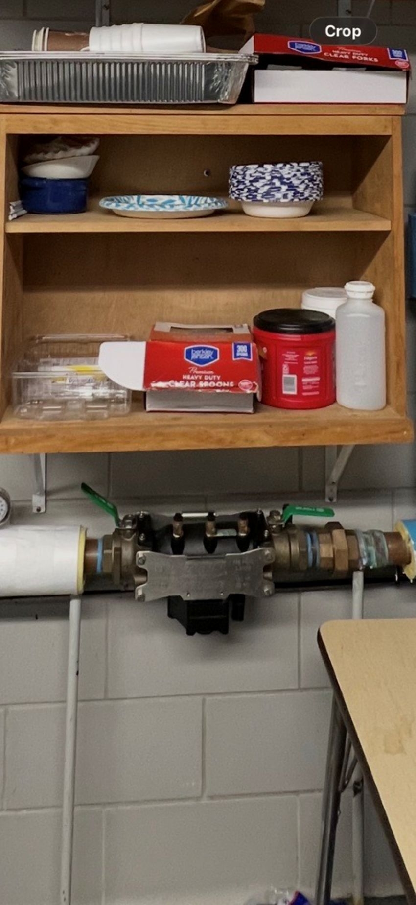
Common contamination risks include fertilizers, pesticides, bacteria and animal waste from irrigation systems; chemicals and dirty water from submerged hoses; treatment chemicals and antifreeze from boilers and heating, ventilation and air conditioning systems; and carbon dioxide or cleaning agents from beverage equipment. Additional risks come from contaminated well water entering public lines and stagnant or chemically treated water in fire suppression systems flowing back into the potable supply. Backflow preventers are selected based on hazard level.
Severe hazards (e.g., chemical treatment, biological pathogens and toxic waste) require an RPZ for maximum protection. Moderate hazards (e.g., fire sprinkler systems with no antifreeze or chemical treatment, commercial heating systems with no rust-inhibiting chemicals added, lawn irrigation systems and food and beverage equipment) use a double check valve assembly. Low-risk back-siphonage conditions (e.g., standard hose bibs, icemakers and ponds or fountains supplied by the potable water system) typically use either pressure or atmospheric vacuum breakers.
For the highest level of protection in any situation, an air gap is the most reliable method as it provides physical separation between potable and contaminated water. It is also important to note that backflow preventers can cause a significant pressure drop in a domestic water system, sometimes more than 20 psi. This must be accounted for when calculating how much water pressure is remaining after the water entrance to serve the plumbing fixtures in the building. In addition to ensuring all proper calculations and provisions are made for the RPZ, water meters require careful attention.
Water meters for domestic water systems
Many types of water meters exist and they all measure water flow being used in the domestic water system (see Figure 5). Examples include compound, disc, turbine, electromagnetic, ultrasonic and fire. Of these, disc-type water meters are the most common for small water service sizes such as single-family homes, apartment buildings with fewer than 100 units, retail stores, restaurants, schools and other public buildings without large irrigation demands. Compound water meters are typical for medium water service sizes such as apartment buildings with more than 100 units, dormitories, schools with irrigation and large retail shopping centers. Disc-type water meters are positive displacement meters that commonly include a nutating disc and a magnetic coupling.
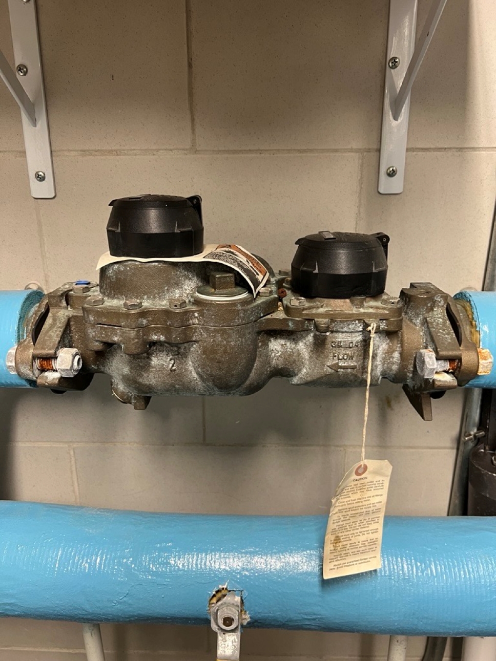
Positive displacement disc meters calculate flow by passing known amounts of water through the fixed-volume measuring chamber inside the meter and counting how many times the volume within is filled and emptied. The frequency of isolated volumes entering and leaving the water meter will be the flow rate through the water meter. Compound water meters are used for both high- and low-flow applications and consist of one low flowmeter (typically a disc meter) and one high flowmeter (typically a turbine meter). Flow in a turbine meter is calculated through the number of electrical pulses created by the rotation of the turbine over time.
Compound meters are used in series or in parallel if not for fire service. In series, compound meters operate simultaneously while one meter registers flow, depending on the amount of flow coming in. Parallel compound meters only have one meter operating at a time and transition to one another via automatic bypass if flow increases or decreases past the threshold of either meter.
After water enters a building and has gone through the water meter, PRVs and backflow preventers, it must be distributed to the plumbing fixtures. However, before sizing the distribution system, building water demand must be determined. The goal of domestic water system sizing is to provide adequate flow and pressure at peak demand without unnecessary oversizing. The first step involves looking at Appendix E of the IPC.
IPC Appendix E Table E103.3(2) assigns cold, hot and total loads to plumbing fixtures in water supply fixture units (WSFUs). WSFUs are based on the theory of probability. Plumbing fixtures are assigned cold, hot and total WSFUs based on the rate at which the fixture consumes water, the length of time the fixture is in use and the average length of time between fixture uses. Hot and cold WSFUs are typically 75% of total potable water load. The engineer will want to use either the cold or hot WSFUs when sizing branch piping for cold or hot water lines.
Main line sizing for domestic water systems
To determine the main line size for the cold water entering the building, the WSFUs for all fixtures are summed. Depending on fixture classification (e.g., private or public offices, hotels and restaurants), the IPC will have a table that lists the fixtures and total WSFUs for the type of fixture and the minimum cold water and hot water connection sizes for the piping on the fixture. To size the main water line entering the building, the engineer first totals the number of each fixture type, then multiplies those quantities by the corresponding WSFU values for each fixture.
After the WSFUs are totaled for each type of fixture, the engineer totals the WSFUs for all fixtures in the building. For example, according to Table E103.3(2) in Appendix E of the 2021 IPC, a public water closest with a flush tank has five WSFUs. If a building is designed to have a total of five public water closets as its only plumbing fixtures, the total WSFUs for the building would be 25 WSFUs.
After calculating the total WSFUs, the engineer will continue using Table E103.3(3) in IPC Appendix E. Table E103.3(3) is used to convert the total amount of WSFUs directly to gallons per minute (gpm). The engineer will determine whether the existing building or new building design is predominantly made up of flush tanks or flush valves for water closets. Table E103.3(3) is divided into two parts: One part converts WSFUs to gpm with flush tanks as the dominant water closet fixture type for the building while the other part converts WSFUs to gpm with flushometer valves as the main water closet type.
For systems that include both flush tanks and flush valves, any part of the cold water system downstream of flushometer valves is considered part of the flush valve system, and any part of the cold water system upstream of flushometer valves is considered part of the flush tank system. This information enables the engineer to determine whether the cold water system is predominantly flush tanks or flush valves in a building where this is not known.
If the domestic water system is determined incorrectly as being predominantly flush valves or flush tanks, using the wrong table results in the wrong design flow for the entire system. For example, if the engineer determines the system to be predominantly flush tanks when it is flushometer valves, the design flow rate using the flush tank column will be lower than when using the flush valve column. A lower design flow rate will likely result in an undersized pipe with excessive velocities and excessive pressure drop. The rated pressure of most water service piping systems is at least 150 psi gauge and many can withstand much higher pressures. However, undersized pipes increase pressure drops and restrict flow rates, which can increase erosion due to increased velocity and cause fixtures not to operate as intended.
For a domestic water system, the engineer will always add the WSFUs together for a conversion to total gpm for the system, but this is not always the case for totaling gpm for fixtures. Gpm values for fixtures are not totaled unless they are for continuous-use fixtures. Examples include laundry equipment and cooling towers. Flows for continuous-use fixtures are added to the total cold water system flow because they place a continuous demand on the system, unlike simultaneous-use fixtures (e.g., water closets), where demand is intermittent.
Once all WSFUs and flows are accounted for in the domestic water system, the engineer can size the piping. After selecting a trial pipe size and using Figure E103.3(3) Friction Loss in Smooth Pipe in Appendix E of the IPC to fit the flow at the water entrance of the building, the engineer will determine how much friction loss (pressure drop) is allowed across the entire piping system using the trial pipe size. In a domestic water system, friction loss occurs through straight sections of pipe, plumbing fixtures and pipe fittings. The engineer must determine the most hydraulically remote fixture from the building water entrance with the highest total pressure drop (critical circuit).
Critical paths for domestic water systems
When determining the critical path for the highest pressure, it can be helpful to view IPC Table 604.3 to understand the minimum pressure required for certain plumbing fixtures. This will allow the engineer to determine which remote fixtures require more water pressure for similar lengths of piping from the water entrance. For example, the minimum required water pressure for a balanced-pressure shower is 20 psi, while the minimum pressure for a service sink is only 8 psi.
To determine the critical path, the engineer will add the flow pressure drops in all appliances and devices in the potential critical circuits and exclude the pressure drops in the pipe itself. This is because the pressure drop across the piping to the most remote fixture must be less than the available pressure after all water meters, PRVs and backflow preventers have been accounted for.
Once the pressure to overcome pipe friction is known, the engineer must determine the equivalent length of pipe to the most remote fixture to which the available pressure drop will be applied. This can be done by measuring the length of the critical circuit and multiplying it by a factor of 1.5 (engineering/industry rule of thumb; not code provision), which will provide an approximation for total friction loss in the pipe where the final size of fittings and valves is not known. With the equivalent length of pipe known, the engineer can calculate the pressure drop across the pipe per 100 feet by multiplying the available pressure to overcome pipe friction by 100 feet over the equivalent length.
Elevation changes in domestic water systems
Note that many plumbing designs require water to travel multiple floors to serve fixtures, which will result in loss to elevation as well. Changes in elevation directly affect pressure, with an increase in elevation reducing available pressure (approximately 0.43 psi per foot of rise) and a decrease in elevation increasing pressure by the same amount, which must be accounted for when sizing the system. With the estimated friction loss per 100 feet and friction loss by elevation, the engineer can now calculate total friction loss from the pipe in the critical circuit. Failing to account for equivalent lengths and elevation changes for pipe fittings and valves can result in sizing a system for less pressure loss, which could prevent adequate water pressure to the most remote fixture. Adequate water pressure allows for adequate flow and velocity through a water pipe.
A rule of thumb for the plumbing engineer is to not exceed 6 feet per second (fps) through any point in the piping system. Ideally, lines are sized based on flows of 4 to 6 fps. Exceeding 6 fps in a piping system for domestic water can cause the system to leak, erode and potentially be annoyingly noisy for building inhabitants. Pipe sizing charts for iron and copper domestic water piping are provided in plumbing codes, American Society of Plumbing Engineers data books and other online sources. Many online sources provided by pipe fitting companies include easy-to-use calculators for selecting pipe sizes based on pipe velocity or pipe friction rate (pressure drop).
Domestic water system design success
Successful domestic water system design extends beyond meeting code requirements. It demands a thoughtful integration of hydraulic analysis, practical engineering judgment and long-term system performance considerations. By understanding how fixture demand, pressure distribution and piping characteristics interact, engineers can create systems that both comply with the plumbing code and operate reliably and efficiently throughout the life of a building.
The ability to evaluate critical circuits, manage pressure losses and properly size piping is fundamental to delivering safe and effective water distribution systems. As commercial buildings continue to grow in complexity and efficiency demands increase, a strong foundation in domestic water design principles remains an essential skill for engineers committed to producing resilient, sustainable and high-performing building systems capable of adapting to evolving industry standards, occupant needs and future infrastructure challenges.