As buildings move away from fossil fuels, AWHPs are emerging to electrify hydronic heating and cooling systems without abandoning the infrastructure many facilities rely on.
Learning objectives
- How AWHPs operate within the vapor compression refrigeration cycle to provide both heating and cooling in hydronic HVAC systems.
- Key performance factors that affect AWHP efficiency, including outdoor air conditions and hydronic supply temperature.
- The major design and retrofit considerations involved in applying AWHPs to existing hydronic systems, domestic hot water systems and hydronic variable refrigerant flow (VRF) systems.
AWHP insights
- By integrating seamlessly with both new and legacy hydronic networks, the AWHP serves as a vital bridge for engineers transitioning buildings from fossil fuel-based heating to electrified, low-carbon systems.
- Optimizing the performance of an AWHP requires a shift in design philosophy toward lower hydronic supply temperatures and improved building envelopes to maximize efficiency across varying outdoor conditions.
The push to decarbonize the built environment has fundamentally reshaped how engineers approach heating and cooling system design. Buildings remain a significant contributor to greenhouse gas emissions, largely driven by fossil fuels combustion for space heating and domestic hot water production. According to the U.S. Environmental Protection Agency, the building sector accounts for 31% of emissions in the United States.

As state and local governments, utilities and corporations establish aggressive carbon-reduction targets, building electrification has emerged as a primary strategy to eliminate onsite emissions. Heat pumps are one of the leading technologies used in decarbonization and electrification efforts.
The transition away from traditional boiler-based hydronic systems is not straightforward, especially in buildings designed around hydronic distribution networks that rely on high-temperature supply water. These legacy systems present both a challenge and an opportunity to electrify buildings without sacrificing building performance, occupant comfort or operational reliability.
Air-to-water heat pumps (AWHP) have gained attention as a practical solution to building decarbonization. Unlike air-to-air heat pumps, which are limited to direct-space conditioning, AWHPs produce hot or chilled water, which allows them to integrate seamlessly with existing or new hydronic systems such as fan coils, radiant floors and condenser water loops. This compatibility positions AWHPs as a bridge between familiar, legacy hydronic systems and building electrification.
In addition, AWHPs provide a pathway to rethinking hydronic supply temperatures and encourage designs that operate at lower, more efficient temperatures.
The decision to adopt AWHPs requires a deep understanding of their performance characteristics and limitations. Their efficiency is inherently tied to both outdoor air conditions and the temperatures required by the hydronic system serving the building loads. Engineers must carefully evaluate whether AWHPs can replace traditional heating, ventilation and air conditioning (HVAC) equipment and how system design and building loads influence overall feasibility.
Vapor compression refrigeration cycle
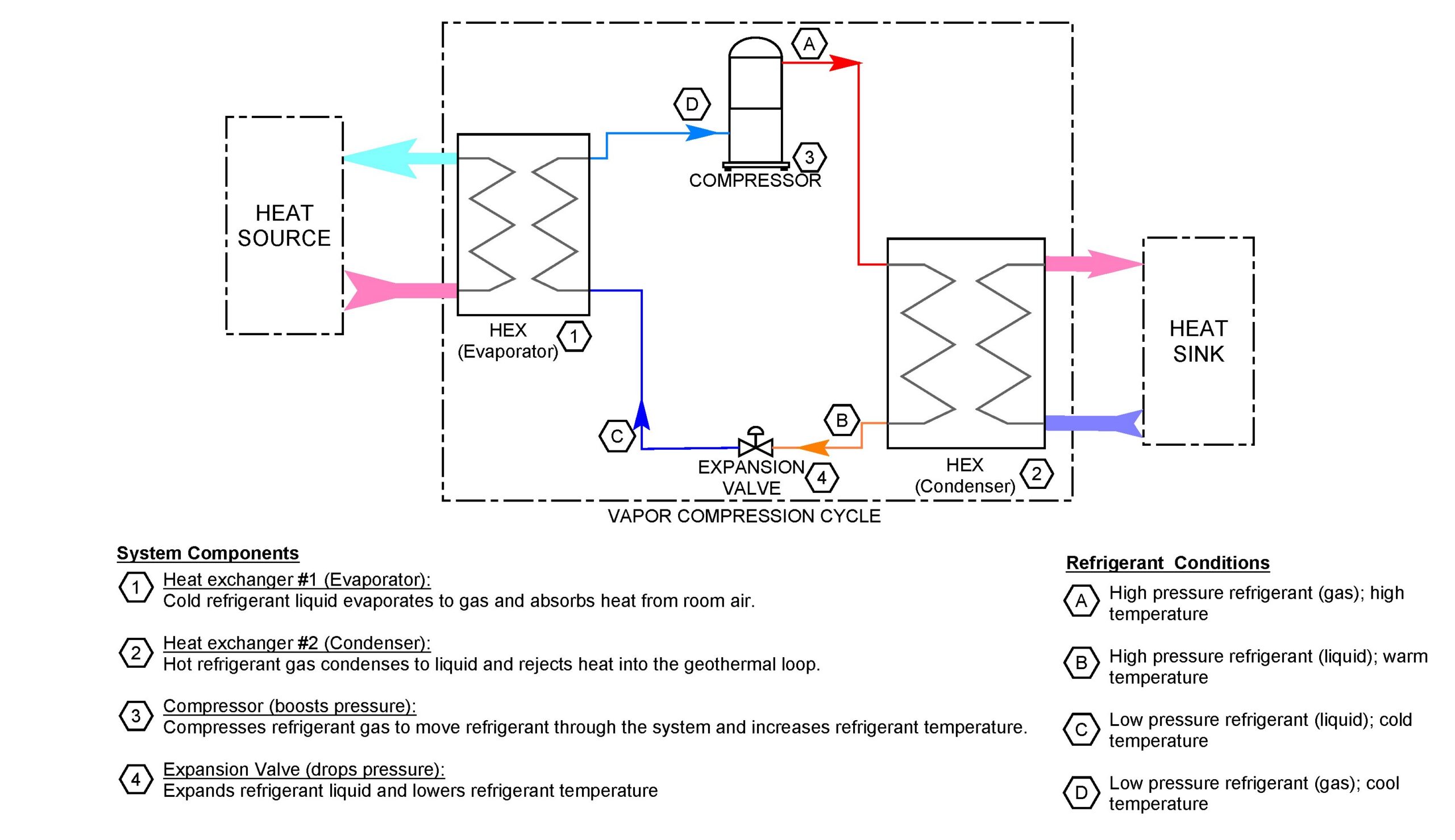
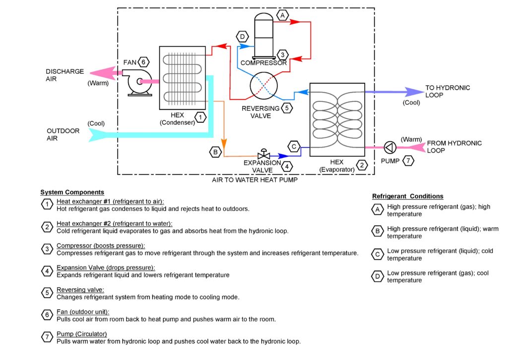
Rather than generating heat through combustion, a heat pump operates by transferring thermal energy from a heat source to a heat sink using the vapor compression refrigeration cycle (see Figure 1). The vapor compression refrigeration cycle consists of four primary components:
- Evaporator: Refrigerant absorbs heat from the heat source as it passes through the evaporator, raising the temperature of the refrigerant to change from a low‑pressure liquid to a vapor.
- Compressor: Increases the pressure and therefore the temperature of the refrigerant to a suitable temperature for heat transfer.
- Condenser: Heat is rejected from the refrigerant to a heat sink as it passes through the condenser and the refrigerant condenses back into a liquid.
- Expansion valve: Reduces the refrigerant pressure and temperature, allowing the refrigerant to return to the evaporator and repeat the cycle.
Most air conditioning units use this refrigeration cycle to remove heat from an indoor building space and reject the heat outdoors to the ambient air. Unlike cooling-only air conditioning units, AWHPs reverse the direction of refrigerant, enabling the same system to provide both heating and cooling. The reversing valve within the circuit changes the direction of refrigerant flow.
In heating mode, the outdoor coil functions as the evaporator by absorbing heat from the ambient air, while the indoor heat exchanger acts as the condenser, transferring heat to the hydronic loop (see Figure 2).
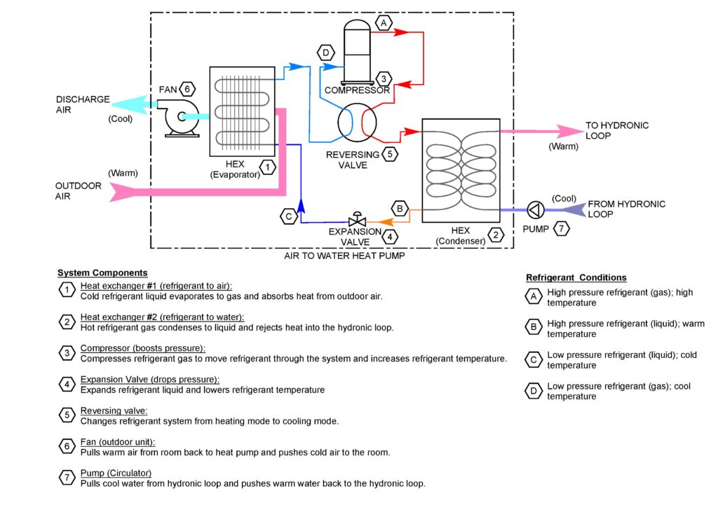
When the system reverses direction and operates in cooling mode, the outdoor coil functions as the condenser, rejecting heat to the ambient air, while the indoor heat exchanger acts as the evaporator by absorbing heat from the hydronic loop (see Figure 3).
By simply reversing the direction of refrigerant flow, the same system can provide both hot water and chilled water by absorbing heat from the heat source and rejecting it to the heat sink.
AWHP efficiency
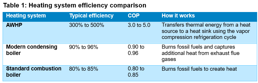
This ability to move heat rather than create it enables heat pumps to operate at high efficiencies, a main driver for the adoption of AWHPs. Traditional combustion technologies are limited to 80% efficiency and more efficient condensing hot water boilers can reach efficiencies up to 96%. Heat pumps can exceed these efficiencies because they transfer more heat than the electricity they consume (see Table 1).
Therefore, according to the International Energy Agency, heat pumps are three to five times more efficient than traditional gas boilers. Heat pumps are typically evaluated using metrics such as coefficient of performance (COP) and energy efficiency ratio (EER) to compare the amount of energy extracted to the energy input.
COP is defined as the ratio of useful thermal energy (heat delivered) to the amount of electric energy consumed by the heat pump. For example, a COP of 3.0 indicates that the heat pump provides three units of heat for every unit of electricity input. COP is a unitless metric and both the energy input and energy extracted should be converted to the same unit of measure (e.g., kilowatts, British thermal units per hour [Btuh]). Heat pump cooling efficiency is expressed as EER, which is the ratio of cooling output (Btuh) to electrical input (watts).
ASHRAE Standard 90.1: Energy Standard for Buildings Except Low-Rise Residential Buildings outlines the minimum efficiency requirements and test procedures for heat pumps and other equipment in Chapter 6.8, Minimum Equipment Efficiency Tables. The International Energy Conservation Codereferences ASHRAE 90.1 within Section C403.3.2, HVAC Equipment Performance Requirements, which also outlines the minimum efficiency requirements and test procedures for heat pumps and other building mechanical system equipment.
Real-world performance is more complex than single-point efficiency ratings because heat pumps rarely operate at rated conditions. Instead, AWHPs operate across a wide range of part-load scenarios driven by fluctuations in outdoor air temperatures and building loads.
Commercial-scale AWHPs are typically evaluated using a combination of full- and part-load efficiency metrics. Seasonal COP aggregates efficiency over multiple temperature bins and part-load conditions to represent averages, like heating seasonal performance factor.
Part-load cooling performance is characterized by integrated energy efficiency ratio (IEER), integrated part-load value (IPLV) and nonstandard part-load value (NPLV), which combine efficiency measured at several discrete load points with weighting factors.
IEER uses a standardized weighting that emphasizes typical part-load operation, while IPLV is designed by AHRI under fixed rating conditions. NPLV applies the same methodology but uses project-specific temperatures and load assumptions, providing a more customized estimate of part-load performance.
These metrics account for variations in capacity, cycling losses and control strategies over time. It is important for engineers to evaluate performance curves and understand how equipment responds to changing conditions rather than relying solely on the nominal equipment ratings. Heat pumps can be more efficient at part-load conditions by modulating their capacity to match the load. At part-load conditions, cycling losses are reduced and the heat pump can operate at lower temperature differences across the heat exchangers, increasing the COP.
AWHP performance
The performance of AWHPs depends on several variables. Both COP and EER are highly sensitive to temperature lift, the difference between the outdoor air ambient temperature and the load temperature (hydronic supply temperature). As the temperature lift increases, the compressor must perform more work (increasing electric input) to deliver the same amount of thermal energy output, decreasing the efficiency.
In northern climates, decreases in outdoor air temperature increase the temperature lift, decreasing efficiency and heating capacity. This is further compounded by defrost cycles, which temporarily reverses the operation, to melt ice or frost from the outdoor coil and reduces the net heating output.
It is crucial to select and design AWHPs to operate in low ambient conditions for cold-climate applications by reviewing performance curves at low ambient conditions, not just rated values. Cold-climate heat pumps are engineered with features such as enhanced vapor injection, larger heat exchangers and variable speed compressors that allow them to maintain capacity and efficiency at low outdoor air temperatures rather than relying heavily on supplemental heat.
However, operating in low ambient conditions does not necessarily mean operating at full capacity. Like all AWHPs, the COP and available heating capacity are reduced as outdoor air temperatures decrease.
Minimizing temperature lift by pairing cold-climate AWHPs with lower hydronic supply temperatures, such as those between 120° and 140°F, significantly improves their performance at low outdoor air temperatures. Traditional hydronic systems are designed for 180°F supply temperature water, which requires a significantly higher temperature lift compared to modern low-temperature systems.
However, retrofitting existing hydronic systems from traditional 180°F supply temperatures to more moderate temperatures has its challenges. Existing coils in equipment sized for a higher temperature difference between the hydronic supply and the space temperature will experience a decrease in heat output when the hydronic supply temperature is decreased. Sometimes, the decrease in heating capacity of the coil is so dramatic that the coil no longer meets required peak heating loads. As a result, retrofits frequently require either larger or additional heat transfer surfaces such as upsized coils, added radiation or conversion to low-temperature equipment.
Many legacy buildings rely on high supply temperatures to compensate for building envelope deficiencies. Poor insulation, air leakage and older windows increase heating loads, making it difficult to maintain occupancy comfort with lower supply temperatures. Reducing supply temperature without addressing the underlying heating load issues can lead to occupant discomfort and inability to meet peak heating loads during design winter conditions. Envelope improvements and load reduction strategies are often a prerequisite for successful low-temperature conversions.
Lowering system supply temperature also has system level implications tied to the hydronic design. Lower supply temperatures typically require higher flow rates or greater heat exchanger surface area to provide the same heating capacity as higher supply temperatures. This could affect pump sizing, distribution balance and control strategies. Secondary loops, mixing strategies or hydraulic separation could be required to maintain operation across varying loads.
Overall, retrofitting buildings to lower supply temperatures introduces a broader design paradigm shift. High-temperature systems were historically optimized to minimize equipment size and first costs, whereas low-temperature systems prioritize efficiency and compatibility with electric equipment such as heat pumps.
Bridging this gap is rarely as simple as equipment replacement and often requires coordination and redesign. Hybrid or staged approaches such as supplemental heating or phased upgrades should be considered to transition from high supply temperatures to low supply temperatures to balance performance, cost and decarbonization goals.
Two-stage or cascade heat pump configurations can be an effective solution to situations where the required supply temperatures exceed the average operating range of a single AWHP. The first stage generates lower hydronic supply temperatures of 120° to 140°F, while the second stage raises the temperature only where it is necessary. This reduces the overall temperature lift and therefore improves system performance.
In addition, phased implementation could allow retrofit projects to seamlessly integrate AWHPs alongside existing heating systems. Buildings can transition to lower supply temperatures while maintaining reliability during peak conditions by upgrading terminal units, optimizing controls and reducing loads.
Domestic hot water using AWHP
AWHPs are increasingly being applied to domestic hot water (DHW) systems as part of broader building electrification and decarbonization strategies. AWHPs offer a high-efficiency alternative to conventional gas or electric resistance water heaters. In these applications, the heat pump extracts thermal energy from the outdoor air and transfers it to a dedicated DHW storage tank where the energy is stored and distributed.
Unlike space‑heating loads, DHW demand is short duration hand high-intensity peaks typically occur during morning and evening periods in residential applications. Therefore, storage and load management are critical design considerations. Most AWHP DHW systems are designed with insulated storage tanks to allow the heat pump to operate steadily at higher efficiency, while maintaining the ability to meet intermittent peak demands.
Based on guidance in ASHRAE Handbook — HVAC Applications Chapter 51, Service Water Heating, the cold water main temperature is delivered to the building at about 50° to 55°F at design conditions. ASHRAE guidance characterizes cold water temperature as being approximately equal to local ground temperature, which in most climates corresponds to roughly 50° to 55 °F, although this entering cold water temperature varies seasonally and geographically.
Typically, DHW is supplied at 120° to 140°F. This requires a temperature lift of about 70° to 90°F across the heat pump, which can reduce the COP of the AWHP compared to lower-temperature hydronic applications. Many AWHPs address this challenge through using variable-speed compressors and supplemental electric elements.
Despite these challenges, AWHP DHW system can still produce hot water efficiently, often achieving COP values well above electric resistance heating. They also offer opportunities for integration with renewable energy sources, such as using excess photovoltaic generation during peak solar radiation in the day to charge the hot water storage tank when DHW demand is low. Successful applications of AWHP DHW systems require careful attention to temperature requirements, storage sizing and control strategies to balance efficiency, safety and peak demand performance.
VRF systems and refrigerant changeover
AWHPs can also be used with hydronic variable refrigerant flow (VRF) systems, an emerging approach to address both decarbonization and evolving refrigerant safety requirements. Traditional systems rely on direct refrigerant distribution from an outdoor condensing unit to indoor fan coil units, which can introduce challenges related to refrigerant charge limits. This is particularly important in the current context as the industry transitions to lower global warming potential refrigerants such as A2L-class fluids with mild flammability characteristics.
Hydronic VRF systems mitigate this issue by using water as the primary energy transfer medium within occupied spaces instead of refrigerant. The refrigerant is contained in the outdoor condensing unit, often an AWHP and an indoor heat exchanger. This significantly reduces the amount of refrigerant in occupied spaces and stays within the volume limits outlined in ASHRAE Standard 15: Safety Standard for Refrigeration Systems.
The AWHP produces hot or chilled water that is distributed through a hydronic loop to terminal units, which serve zones similarly to a traditional VRF indoor unit but without direct refrigerant piping to the occupied areas. This decoupling introduces additional flexibility in system design, enabling easier zoning, longer distribution lengths and integration with other hydronic loads such as radiant systems or DHW generation.
At the same time, it allows engineers to lever the inherent efficiency advantages of heat pumps operating on low-temperature water loops. Hydronic VRF systems paired with AWHPs provide a pathway to maintain performance while addressing regulatory and safety concerns, positioning it as a compelling solution for future-ready, low-carbon building systems.
AWHP for decarbonization
AWHPs represent a pivotal technology in the transition toward low-carbon building systems, offering a practical pathway to electrify heating while leveraging the familiarity and flexibility of hydronic distribution. As the HVAC industry continues to move away from fossil fuel-based systems, AWHPs bridge the gap between traditional HVAC design and future-focused decarbonizations strategies. The ability to move heat rather than generate it positions AWHPs as a fundamentally different and more sustainable approach to providing both space and DHW loads.
However, successful AWHP applications are not as simple as replacing a boiler with a heat pump. AWHP performance is inherently tied to supply temperatures, climate conditions and building characteristics forcing engineers to rethink long-standing design assumptions. Lower-temperature hydronic systems, improved building envelopes and thoughtful integration with controls and distribution systems are essential to unlocking the full potential of AWHP technology.
Emerging configurations such as low-temperature condenser water loops, DHW production and integration with hydronic VRF systems further demonstrate the adaptability of AWHPs across a range of applications.
AWHPs are not simply a one-for-one equipment substitution. AWHPs represent a shift in design philosophy that aligns building HVAC systems with the broader goals of building decarbonization.