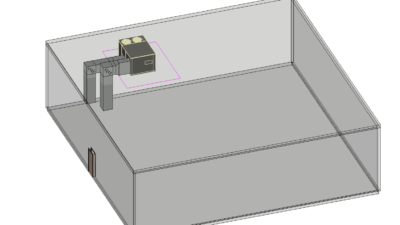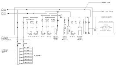
A multizone VAV system was designed for an office building in Florida.
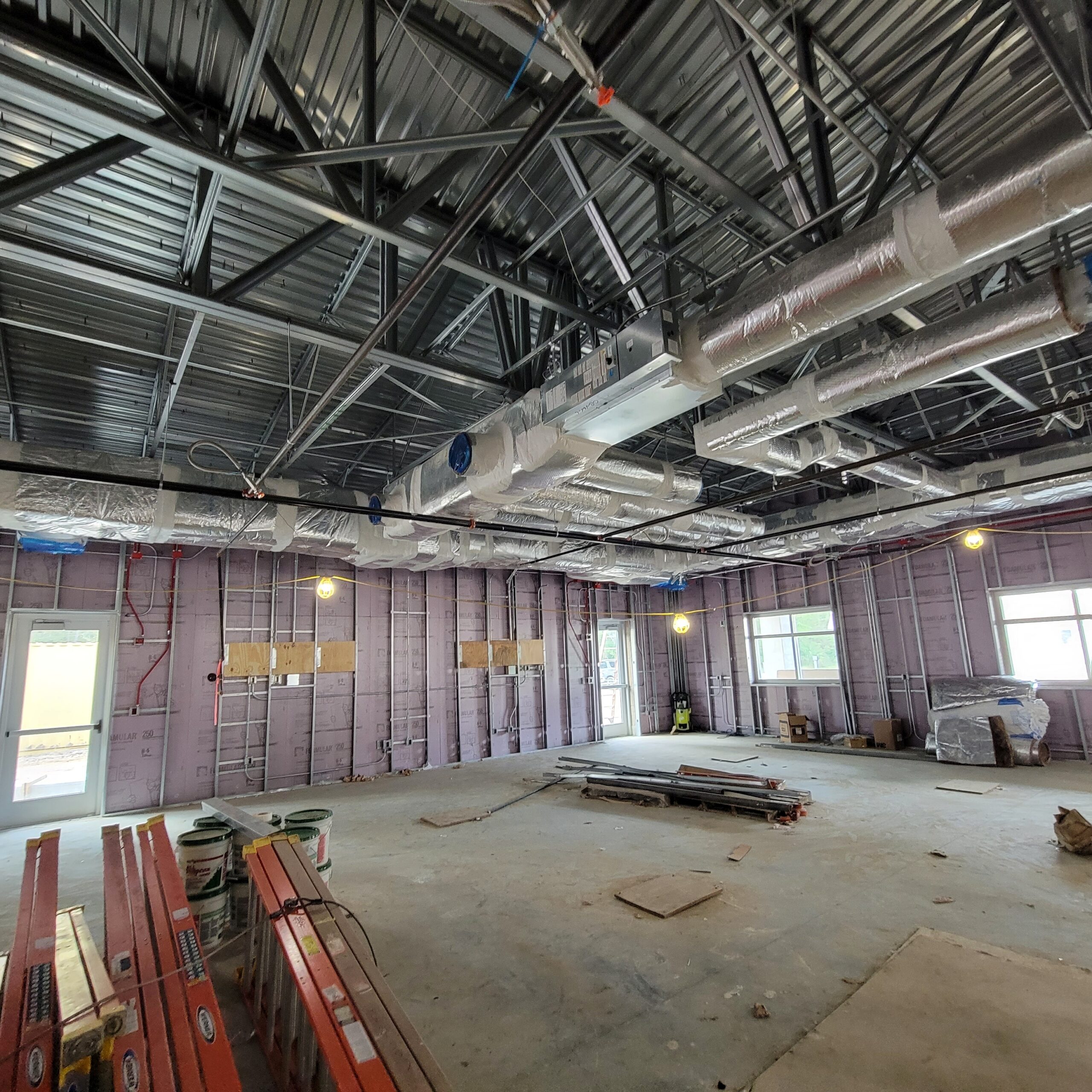
Office buildings are an ideal type of facility for incorporating variable air volume (VAV) systems. This example involves a client-owned operation building in Florida, where a multizone VAV system was used to control various office and laboratory spaces. One air handling unit was designed to provide varying airflows to 21 different zones, of which there were 10 different space types (see Figure 6). The box was installed above an acoustic tile ceiling (not shown) and tapped off a main duct that serves multiple spaces. As shown, there are electrical boxes with controls and heater components that must remain accessible to ensure they are maintained during building operation.
The space types throughout the operations building include a lobby, corridors, janitor closet, storage rooms, locker rooms, offices, control rooms, laboratories, conference rooms and a breakroom. See Table 3 for the various ventilation requirements for these spaces using Chapter 6 of ASHRAE Standard 62.1: Ventilation and Acceptable Indoor Air Quality. The initial total design exhaust was 825 cubic feet per minute (cfm), total design supply was 12,550 cfm and total outdoor air (OA) was 854 cfm.
Worst-case scenario ventilation calculations typically assume that all spaces have the potential to be occupied simultaneously to ensure adequate OA is supplied when all spaces are occupied. If all spaces in this operations building are occupied, there would be a population of 45 people.
However, considering that spaces such as the break room and smaller conference room may not be fully occupied while all offices are occupied, the population is closer to 35 people occupying the spaces within the VAV system zones. This results in an occupant diversity ratio of D = 0.78 (35/45). Because the occupant diversity is higher than 0.60, the system’s ventilation efficiency would be 0.75 (ASHRAE 62.1, Section 6.2.4.3.1). Therefore, the final design OA intake requirement is 825 cfm/0.75 = 1,100 cfm, using an air density correction factor of 1 as the project location is very close to sea level.
Evaluating each zone individually using heating mode as a worst-case scenario, an effectiveness (Ez) value of 0.8 would be used for each zone. Both supply and return diffusers are on the ceiling for all zones in this operations building. Corrected OA for each zone is calculated by dividing the OA required for each space by the Ez value of 0.8 (see Table 3).
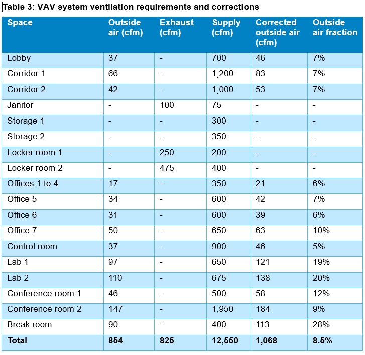
The space with the highest percentage of OA relative to supply requirement is the break room at 28%. This space is considered the critical zone, requiring the entire VAV system to supply 28% OA to satisfy this space. For the system, 12,550 cfm × 28% = 3,530 cfm, which is much higher than the original 8.5% total system OA requirement.
This requirement can be offset by increasing the supply air to the one space — from 400 to 500 cfm — which lowers it to 23% OA and only requires 2,846 cfm OA to be mixed into the system. The system results would be 12,550 cfm supply, 825 cfm exhaust and 2,850 cfm OA.
The next steps to consider were how the OA levels will be controlled to ensure proper airflow throughout the day. This system, like many VAV systems, was provided with direct digital control to control the total airflow of the system throughout the day. Inputs such as the minimum outside air flow setpoint and VAV box minimum supply air setpoint ensure appropriate ventilation is provided to each zone.
The outside air system is controlled with an OA intake louver equipped with a motorized damper. This was ducted to the return of the AHU serving the VAV system, which was set to be open during occupied periods. This sequence ensures that adequate OA is delivered when the building is in use, supporting ventilation requirements and occupant comfort. During unoccupied hours, the damper closes to limit unnecessary intake of unconditioned air, reducing energy consumption and improving overall system efficiency.
Incorporating this control strategy also helps maintain compliance with ventilation standards while balancing performance and energy savings across varying operating conditions. By coordinating OA levels with real-time demand, the system can better support ventilation requirements, energy efficiency and overall indoor air quality.
Additional consideration should be given to how these control sequences integrate with occupancy patterns, economizer operation and any minimum ventilation setpoints to ensure consistent performance across all operating modes.