An understanding of the basic operations between a grounded and an ungrounded electrical system is necessary for matching the appropriate grounding topology to the electrical system performance.
There are various benefits for grounding and bonding ac transmission and distribution power systems. The basis for selection of a given grounding system type depends on its ability to provide personnel safety and equipment protection. Primarily, the electric power industry is concerned with reducing shock and flash hazards to personnel working with electrical systems, limiting damages to the electrical system components due to transient overvoltages, and minimizing interruption to the commercial or industrial processes that the electrical system supports.
Based on these criteria, the prevailing grounding design philosophy is to provide a grounded system over an ungrounded one for satisfying these objectives. Nevertheless, an understanding of the basic operation of each type of system is necessary for matching the appropriate grounding topology to the electrical system performance. Commercial buildings, with most of their equipment operating at 600 V and less, seem to have standardized on a solid grounding and bonding approach. Proper application of this approach is done through the lens of the National Electrical Code.
Reasons for grounded and ungrounded systems
According to the NEC, there are two main purposes for grounding the electrical ac system: one is to stabilize the system voltage to earth during normal operating conditions by providing an earth’s reference frame for the system; the other is to maintain within acceptable limits, excess voltages on the system due to lightning, line surges, and incidental contact with higher voltages. These two reasons allow the design engineer to meet the two primary goals of equipment protection and personnel safety for the electrical system. A third goal for grounding is to allow the processes supported by the electrical system to continue in the presence of a faulted condition. This is usually achieved by either an ungrounded system or by application of a specialized form of grounding (high-resistance grounding).
Power systems in the 1950s tended to be ungrounded, 3-phase, 3-wire, with delta transformer and delta generator configuration. The main benefit of this grounding configuration is that it allows a single bolted phase-to-ground fault to operate indefinitely without damage at the faulted location, and without tripping of a protective overcurrent device. This provides continuity of service while the faulted conductor is located, albeit with shock hazard risk to personnel. However, the majority of ground faults are not the bolted type, but the low-level arcing (restriking) type. These restriking ground faults, because of their relatively low fault currents, can go undetected by ground-fault monitoring equipment. The danger here is that the restriking ground faults produce escalating transient overvoltages on the conducting system insulation. If left unchecked, the voltage stress on the system insulation can lead to a double line-to-ground fault, which would result in the unwanted tripping of the protective overcurrent devices. An even worse scenario would be the destructive arc-flash hazard consequences. For this reason, ungrounded systems are less likely to be constructed now, and are more likely to be upgraded with some type of an impedance grounded system.
There are various points on the electrical system available for grounding, such as the midpoint of a single-phase transformer, corner of the delta windings, or the center of the wye windings. The points that are considered the neutral point of the system are most commonly used for grounding. The neutral point affects, and is in turn affected by, the other three phases identically on a balanced 3-phase system. By its nature, this point presents the best opportunity to realize the two main purposes for grounding the electric power system. The grounding methods described below involve connection to the neutral point of a wye system (generator or transformer). In general, where neutral points for grounding are not available on the generator or transformer windings as in a delta connection, grounding transformers such as zigzag or wye-delta transformers are used. These grounding transformers effectively create a neutral connection that can then be grounded.
Types of grounding
High-resistance grounding (HRG), with its application in the voltage range of 480 V to 13.8 kV, provides a means for limiting the problems with transient overvoltages associated with ungrounded systems while still providing the benefits of service continuity. The ideal voltage range is 5 kV and less. In general, increasing the ground-fault current flow improves overvoltage control but elevates the point of fault damage. Conversely, decreasing the ground-fault current elevates overvoltage but decreases point-of-fault damage. Correct application of HRG in the medium-voltage (MV) range of 2.4 to 13.8 kV would require a maximum limit on the single line-to-ground, point-of-fault ground-fault current to a value below 7 amp. In addition, the inherent line-to-ground capacitive charging current must be less than or equal to the current through the grounding resistor. Mathematically, the ground-fault current is the vectorial sum of the grounding resistor current and the capacitive charging current. The capacitive charging current is a function of the electrical system that must be initially estimated. With these quantities and conditions satisfied, the range of HRG ground-fault currents can be calculated.
Low-resistance grounding (LRG) schemes are designed to limit ground-fault currents in the range of 100 to 400 amps on systems with voltage ranges of 480 V to 15 kV. With this increase ground-fault current magnitude, the LRG aim is to eliminate overvoltage transients at the expense of increasing the point-of-fault, ground-fault damages. In order to minimize these damages, however, a system of protective devices is formed as part of the LRG scheme. Ideally, the fault is isolated while the rest of the electrical system continues to function. At the higher magnitude of ground-fault currents, the capacitive charging current to ground has very little impact on sizing the grounding resistor. This resistance is then simply the line-to-neutral voltage across the grounding resistor divided by the ground-fault current.
Reactance grounding (RG) is another alternative used on MV systems in the range of 2.4 to 15kV. With this grounding scheme, an inductor is used to limit the flow of ground-fault currents. It has been shown that reactance grounded systems produce transient overvoltages at much higher ground-fault currents than resistive grounded systems. In order to limit the transient overvoltages to acceptable limits, the resulting ground-fault current could be as much as 60% of the 3-phase bolted fault. Since this is much higher than the 400-amp limit for LRG at the same voltage range, reactance is not as commonly used in the electrical industry, except for tuned reactance grounding.
Ground-fault neutralizer (GFN) is another form of reactance grounding known as tuned reactance grounding. As the name implies, the inductive reactance is tuned to the ungrounded phase natural capacitive charging current to ground. This tuning effect by the inductive reactance essentially cancels (neutralizes) the current contribution from the capacitive charging current. This leaves a small portion of the ground-fault current that is essentially resistive in nature. This resistive neutral-to-ground current is in phase with the neutral to ground voltage. The benefit of this phase unison is that an arcing fault to ground is less likely to be sustained by the voltage when the ac current and voltage reach their zero value simultaneously. The GFN application is similar to the HRG application, in that the ground fault is allowed to persist so that the electrical service is continued. Detection of the fault is provided by a coordinated set of ground-fault relays. GFN drawback is similar to RG in that reactance grounding in general tends to increase transient overvoltages. Plus, the grounding circuitry has to be re-tuned after any switching arrangement is made to the electrical system.
Solid grounding (SG) was usually the solution more than 60 years ago when engineers were looking for an alternative to address the problem of transient overvoltages due to arcing ground faults on ungrounded systems. Even though its application was not as successful in the 2.4 to 13.8 kV range due to high point-of-fault energy, SG is consistently applied at voltages below 600 V even today. A solidly grounded neutral system will produce the maximum fault current for a given faulted condition. Therefore, it provides the best opportunity for early detection of arc-flash hazards on the electrical systems. The overcurrent device coordination which is an essential part of the SG system ensures that only the faulted circuit is isolated while the rest of the system continues to function.
Boundary (grounding zone) of the electrical system
The ground-fault effects of the various grounding schemes outlined above are confined within specific areas of the electrical systems known as grounding zones or grounding systems. The boundaries of these grounding systems are created by demarcations such as the primary delta windings of transformers, or the dc point of ac/dc inverters and converters. These systems that are magnetically coupled together, or electrically isolated, except through some form of equipment bonding are considered separate systems.
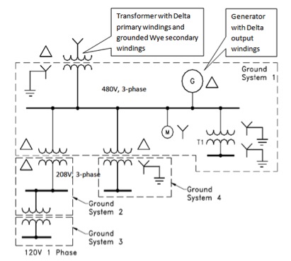
In Figure 1, the 480 V, 3-phase system includes the primary delta windings of Systems 2 and 4, the ungrounded wye connected motor, the solidly grounded wye-wye transformer, the ungrounded delta winding source generator, and grounded wye secondary of the source transformer. System 2 has an ungrounded delta transformer secondary, and an ungrounded single-phase transformer primary. System 3 has an ungrounded single-phase transformer secondary, and System 4 has a grounded wye transformer secondary.
When separate systems develop their own bonding and grounding connections, they are called separately derived systems (SDSs). Power sources such as transformers and generators are usually configured as SDSs. However, when they are electrically connected to another system, they become part of that system and are classified as non-SDSs. Transformer T1 and generator G in Ground System 1, Figure 1 are considered non-SDS.
Commercial building transformer solid grounding
Commercial building transformers are usually connected as SDSs. The main characteristic of the SDS is the bonding of the grounded neutral conductor to the bonded equipment enclosure or to the bonded ground bus. For transformers, there are two configurations for making this neutral-to-ground solid connection. The first configuration has this connection at the transformer itself (see connection A at transformer in Figure 2).
The second configuration has this neutral-to-ground connection at the first disconnecting means downstream of the transformer (see connection C at 208 V panel in Figure 2). This second grounding and bonding configuration is identical to what is required for commercial building service entrance equipment that is served by a utility transformer. In this case, the neutral-to-ground connection is called the main bonding jumper. A third bonding connection B is also indicated. The three A, B, C connections cannot be used simultaneously as this would establish a parallel path for the grounded conductor. However, any two of the three A, B, C connections will be a code compliant installation based on 250.30(A)(1) NEC. In general, the building single transformer grounding and bonding installation can be expanded to multiple transformer arrangements where there are several transformers per floor of a multistory building. This is done by extending the common grounding electrode conductor either vertically through floors, or horizontally within each floor.
Commercial building generator solid grounding
Commercial building generators grounding and bonding connections can be done as either an SDS or a non-SDS. The choice of which configuration to use is determined by the choice of the transfer equipment that will transfer power connections from the utility to building generator(s) upon loss of utility power. If the transfer equipment (switch) allows switching of its neutral connections (i.e., 4-pole), then the generator connected to the transfer switch has to be connected as an SDS. This arrangement will ensure conformity to the safety performance requirements of 250.6(B), NEC (see Figure 3). If the transfer switch does not allow switching of its neutral connections (i.e., 3-pole), then the generator has to be connected as a non-SDS, to again comply with 250.6(B), NEC (see Figure 4). Even though there is no neutral-to-ground connection at generator G2, the generator is not considered ungrounded. This is because the neutral connection of the generator, while not connected to ground at the generator itself, is connected to the ground at the service entrance equipment MDP via the transfer switch. Also, the frame of the generator is grounded with an auxiliary grounding electrode in compliance with 250.54, NEC. This grounding electrode provides the same benefit at the generator that grounding an electrical system will provide.
Multiple generators serving a commercial building tend to be connected as SDSs. This is so because of the requirements for ground-fault devices at facilities large enough to require multiple generators. For instance, proper functioning of these ground-fault devices necessitate that the generators be connected as SDSs. Generators connected in parallel pose special problems in the form of grounding methods and equipment protection. Suffice to say here that matching the electrical parameters of these paralleled generators minimizes circulating third harmonic currents that can affect ground-fault overcurrent devices.
Paralleled generators grounding can be implemented with a common neutral bus connected to a single ground bus, or with individual neutral buses connected to their respective ground buses. In order to use the parallel lineup with the common neutral bus, the switchboard with generator overcurrent devices has to be adjacent to the generators themselves. This is because the neutral-to-ground connection on the SDS has to be at the generators or at the first disconnecting means downstream of the generators (250.30(A)(1) NEC). By this code requirement, if the generator switchboard were to be located remotely from the generators themselves, then the neutral-to-ground bond would have to be at the integral overcurrent device of each generator. It must be stressed here that this application of solid grounding for generators described above is not common practice for generators with voltages above 600 V. This is because the single line-to-ground faults under solid grounding at these higher voltages tend to be greater than the 3-phase bolted faults that generator manufacturers design their generators to handle.
Regardless of whether generators or transformers are grounded as SDSs or non-SDSs, if they serve a specific commercial facility, then all grounding electrodes are required (250.50 NEC) to be bonded together to form a grounding electrode system. This increases the integrity of the building grounding system while not violating the requirements for different grounding zones because the current carrying conductors are not interconnected between grounding zones.
Conclusion
There are several schemes for grounding and bonding transformers and generators. They include ungrounded, impedance grounded, and solidly grounded. The impedance grounded systems are sub-divided into high resistance, low resistance, reactance, and tuned reactance. Ungrounded systems, which at one time were one of the most widely used grounding systems, are currently the least used grounding method. The ungrounded system is designed to allow the first ground fault to exist indefinitely to facilitate service continuity while the fault is located. Unfortunately, the system under this condition, tended to develop transient overvoltages which led to equipment and conductor insulation failures.
In an effort to strike a balance between service continuity and the reduction of transient overvoltages, other impedance grounding schemes and solid grounding were developed. At voltages above 600 V, solid grounding is not as widely used because of the higher point-of-fault energy levels. However, at 600 V and less, solid grounding is the de facto standard for commercial buildings transformers and generators. At this lower voltage, solid grounding, with its inclusive coordinated overcurrent devices, is designed to quickly isolate ground-faults. In this way, only the faulted portion of the system is out of service, while the remainder of the system continues to operate.
Explanation of terms
A grounded electrical system is one in which at least one conductor from the system, or point on the conductive system, is connected to either earth or some other conducting body that serves in place of the earth. This connection can be with or without an intermediary impedance device. With an extremely low-impedance device, the system is said to be solidly or effectively grounded. With an impedance device, the system can be either resistively or reactively grounded.
A bonded electrical system is one in which the non-current-carrying conductive materials of the electrical system are connected together in such a way that they present a low-impedance path for ground-fault currents. This bonded connection permits phase-to-ground-fault currents on the grounded system to flow back to the electrical source for subsequent safety actions by the system. Because of the interconnectivity of a grounded and bonded system, a bonded system also aids the objective of a grounded system.
An ungrounded electrical system has no direct connection between the system conductors and earth or ground, except through the very high naturally occurring reactance due to the line-to-ground capacitive coupling. Regardless of the name’s implication, the NEC still requires the conductive equipment enclosures of an ungrounded system to be grounded for the same reason a grounded system is required to be grounded. This code also requires that an ungrounded system be bonded similarly to a grounded system to provide a low-impedance path for phase-to-phase fault currents to circulate back to the source.
Ground-fault currents are unwanted flow of electrical currents on the electrical system due to unintentional connection between an ungrounded conductor of an electric circuit and earth. Ground faults on average make up 95% of all faults on the electrical systems, with the most common type of ground faults being the arcing type. All forms of grounding and bonding attempt to minimize or eliminate ground faults. Therefore, the various grounding methods mentioned will be in the context of treating ground-fault currents.
Alexander is a senior electrical engineer with exp. His expertise is in electrical engineering for building systems, and he works primarily in commercial and governmental buildings.
References
L. J. Kingrey, R. D. Painter, A.S. Locker, “Applying High-Resistance Neutral Grounding in Medium-Voltage Systems,” IEEE Trans. Ind. Appl., vol. 47, No. 3, May/June 2011.
D. D. Shipp, F. J. Angelini, “Characteristics of Different Power Systems Neutral Grounding Techniques: Fact & Fiction,” Cutler-Hammer, 1988.
D. Paul, S. L. Venugopalan, “Low-Resistance Grounding Method for Medium-Voltage Power Systems,” ICF Kaiser Engineers, 1991.
B. Bridger Jr., “High-Resistance Grounding,” IEEE Trans. Ind. Appl., vol. IA-19, No. 1, January/February 1983.
L. A. Bey, J. Iverson, “Grounding of AC Generators and Switching the Neutral in Emergency and Standby Power Systems, Parts 1 and 2,” Cummins Power Generation, 2006.
K. J .S. Khunkhun, J. L. Koepfinger, M. V. Haddad, “Resonant Grounding (Ground Fault Neutralizer) of a Unit Connected Generator,” IEEE Trans. Ind. Appl., vol. PAS-96, No. 2, March/April 1997.
J. R. Dunki-Jacobs, “The Effects of Arcing Ground Faults on Low-Voltage System Design,” IEEE Trans. Ind. Appl., vol. 1A-8, No. 3, May/June 1972.
IEEE Recommended Practice for Grounding of Industrial and Commercial Power Systems, IEEE Std 142, 2007.
IEEE Recommended Practice for Emergency and Standby Power Systems for Industrial and Commercial Applications, IEEE Std 446, 1995.
National Electric Code Handbook, National Fire Protection Assn., 2011