Engineers designing electrical infrastructure to support smoke control systems must be aware of the stringent requirements listed throughout multiple code sections
Learning objectives
- Know the applicable codes that affect smoke control system electrical design.
- Learn how to provide proper fire protection design for wiring supporting smoke control systems.
- Understand the difference between a smoke control system and a smoke removal system and how that will affect the electrical design.
Smoke control systems are a critical piece of infrastructure that play an important role in the overall fire protection design of a building. When we think about the design of smoke control systems, the focus is often placed on the mechanical design of the system; this makes sense since the main components of these systems are fans that provide positive or negative pressure to a space.
However, it can be easy for design engineers and inspectors to overlook the electrical design of these systems. To provide a design that is safe and code compliant, engineers must have a complete understanding of the requirements of the International Building Code, specifically section 909.
Standby power
One of the most important aspects of the electrical design of a smoke control system is the reliability of the system. When we think of reliability, one of the first things that usually comes to mind is a backup power source. Standby power is a requirement listed in multiple places in IBC 909 (909.11, 919.20.6.2, and 909.21.5). Smoke control systems must be served by a standby power system that complies with IBC Section 2702 and NFPA 70: National Electrical Code Section 701.
Two of the main requirements listed in these sections for standby power systems are that they must provide power to the standby loads within 60 seconds of loss of normal power and they must have enough fuel to operate for a minimum of two hours without being refueled.
A standby power system requirement specific to IBC 909 is that the power source and its transfer switches must be located in a one-hour fire–rated room separate from the normal power equipment and also must be ventilated directly to and from the exterior (IBC 909.11.1).
It is also important to understand that standby power is not the same as emergency power in the way that the codes define it. Emergency power systems have their own dedicated transfer switch that cannot be shared with standby power loads; typical emergency system loads are egress lighting, emergency voice communications systems and fire alarm systems.
Electrical fire protection considerations
Another electrical design consideration for smoke control systems that may be even more important than providing standby power is the overall fire protection design of the electrical system. This is important because providing standby power does not make a difference if the wiring from the standby power distribution equipment to the smoke control equipment is not properly protected during a fire event.
The most stringent electrical fire protection requirements in IBC 909 are for smokeproof enclosure ventilation systems. A common application of a smokeproof enclosure ventilation is a pressurized interior exit stairwell. IBC 909.20.6.1 has a long list of design options and exceptions, the intent of which is to provide two-hour protection for the equipment, power wiring, control wiring and ductwork associated with the smokeproof enclosure ventilation system. This requirement makes sense since an interior exit stairwell is typically two-hour rated and we want to provide the same level of protection for the ventilation system that serves that stairwell.
To provide this two-hour protection, the design engineer must carefully plan out the wiring pathways for not only the branch circuit wiring to the stairwell pressurization fans, but also the feeders that connect the branch circuit panelboards to the upstream distribution equipment. Any wiring located inside the building that is not protected by a two-hour enclosure or room must be either a two-hour listed electrical circuit protective system (see Figure 2), such as mineral–insulated cable or encased within a minimum of 2 inches of concrete.
Encasing conduits in concrete above a ceiling is not always practical and MI cable is significantly more costly than standard wiring methods, so it is advisable to use underground conduits and risers through two-hour rated rooms or through the smokeproof enclosure itself (see Figure 3) as much as possible to avoid difficult and costly wiring installations.
Figure 3: In contrast, to Figure 2, this shows the routing of stair pressurization wiring through two-hour rated enclosures. Courtesy: SmithGroup[/caption]
Elevator hoistway pressurization systems differ from smokeproof enclosure ventilation systems in that two-hour protection for the fan system and its associated wiring is not specifically required. The code requires that the fan system that provides the pressurization be protected with the same fire–resistance rating that is required for the elevator shaft enclosure (IBC 909.21.4.1). For example, if the elevator shaft enclosure is one-hour rated, any portion of the power and control wiring that is not located within the elevator shaft must have a fire resistance rating of at least one hour.
The same strategies discussed for smokeproof enclosure wiring routing can be used for one-hour rated elevator hoistways to avoid special wiring methods. If routing wiring outside of one-hour enclosures cannot be avoided, the engineer could again specify MI cable to provide a fan system that will have a fire rating equal to or greater than the hoistway.
However, MI cable carries a two-hour rating, which is more than what is required in this application and has a significant cost premium. In this case, it may be a better approach to use a wiring method with a one-hour rating. One such system is the UL FHIT electrical circuit integrity system No. 25B, which consists of a specific type of RHW-2 wiring in electrical metal tubing conduit. This system is rated for two hours in horizontal installations and one hour in vertical installations. It should be noted that the manufacturer for both the wire and the conduit must be exactly those that are specified in the UL specification, otherwise the system fire rating is void.
For other smoke control systems that do not serve smokeproof enclosures or elevator hoistways, such as atrium smoke exhaust systems (see Figure 1), the exact fire rating requirement for the fan system wiring is not as straightforward. One applicable section that can help inform the design is IBC 909.4.6, which states that all portions of smoke control systems shall be capable of continued operation after detection of the fire event for either 20 minutes or 1.5 times the calculated egress time, whichever is greater. A conservative approach to addressing this requirement would be to specify one-hour rated wiring methods, as this would ensure continuous operation of the smoke control systems during the building evacuation.
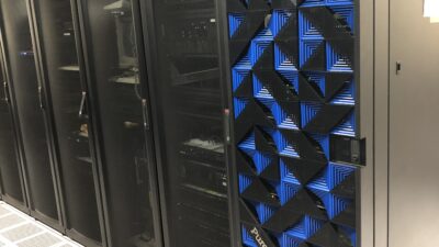
Engineers also need to consider the fire ratings of rooms that house equipment serving smoke control systems. For example, all smoke control fans require a motor controller (see Figure 4); this motor controller should be located in a room with a fire rating that is equivalent to the minimum duration of operation or fire rating that is required by IBC 909. If a motor controller for a stairwell pressurization fan is located in a room with less than a two-hour fire rating, this is a weak point in the system that may compromise the overall integrity of the smoke control fan system during a fire event.
Fire alarm integration
The fire alarm system needs to be considered as equally important system component, as the overall smoke control system will not function properly without these inputs and outputs. Similar to power wiring, IBC 909 has requirements that are intended to increase the reliability of the fire alarm wiring. All fire alarm wiring that serves inputs and/or output signals to the mechanical smoke control system must be fully enclosed within a continuous raceway (IBC 909.12.2). The term “continuous raceway” effectively disallows the use of open wiring methods or metal-clad cable for these specific fire alarm circuits; an enclosed raceway such as EMT must be used.
The fire rating requirements applied to the power system wiring also should be matched for the fire alarm wiring to ensure the system remains fully functional. If a stairwell pressurization system is being activated by a fire alarm relay module, the wiring to that module must carry a two-hour fire rating (IBC 909.20.6.1). For low–voltage systems, there are fire–rated wiring products available that can still be installed in a raceway system like any other standard fire alarm cable.
Circuit integrity (Type CI) cable is available in shielded or unshielded cable assemblies and is listed as a two-hour fire-rated wiring method for UL FHIT electrical circuit integrity systems 28A, 28B, 28C, 28D, 40 and 40A. Each one of these circuit integrity systems has minor variations, including but not limited to manufacturer, raceway manufacturer, raceway size, number of cables permitted in a raceway, etc. It is critical that the installing contractor is familiar with the specific circuit integrity system they are installing to maintain the fire rating of the cabling.
IBC 909 contains specific requirements that help to determine the proper fire alarm sequence of operations for smoke control systems. For smokeproof enclosure ventilation systems, a smoke detector is required to be placed at the entrance of the smokeproof enclosure and this smoke detector must activate the ventilation equipment upon detection (IBC 909.20.6). Elevator hoistway pressurization systems must be activated upon smoke detection in any of the elevator lobbies or when the fire alarm system is in an alarm state (IBC 909.21.6). For other types of smoke control systems, the exact placement of smoke detectors that will activate the smoke control equipment must be determined by the engineer (IBC 909.12.4).
Firefighter’s smoke control panel
A key component in any smoke control system is the firefighter’s smoke control panel. This panel serves as a master station that a firefighter can monitor damper and fan status, manually control fans or override automatically controlled fans. The smoke control panel must be located in a fire command center (if present); in buildings that do not require a fire command center, the panel must be located adjacent to the fire alarm control panel, at a location approved by the authority having jurisdiction (IBC 909.16).
IBC 909 contains very specific requirements for the graphical representation of the smoke system as well as the indicating light colors (IBC 909.16.1). There are also specific requirements for how smoke control system components must be controlled at the panel (IBC 909.16.2, 909.16.3). Engineers should show a detailed diagram of the smoke control panel on the construction documents (see Figure 5); this provides the contractors, plan reviewers and inspectors a clear understanding of what is required.
Smoke control equipment listing
One item to note when specifying a fire alarm control panel or smoke control panel is that these panels as well as their individual system components must be listed as smoke control equipment (IBC 909.12). This specific UL listing is known as UUKL.
The UL product specification website is an invaluable resource when writing specifications for UUKL smoke control equipment, as it provides a listing of all of the currently listed manufacturers and their individual components that carry this listing. Engineers should always ensure that project specifications list only manufacturers on this list when their projects require smoke control.
Fan monitoring and control
The question of whether smoke control fans should be controlled by the building management system or the fire alarm system is something that needs to be closely coordinated by the project’s mechanical and electrical engineers. At first glance, it may seem like it makes the most sense to have the BMS handle the fan control, as this system is typically providing status indication and start/stop control for all the other fans on the project.
However, there are a couple of issues with this approach. One common issue is that the BMS and/or its individual components may not have the required UUKL listing. Another potential issue is that the installing contractors may not be experienced with installing fire-rated wiring methods and the installation may not comply with the UL FHIT listing — and that is assuming that fire-rated wiring methods are being provided in the first place.
There are situations where it may be preferable to use the BMS to handle the smoke control system monitoring and control, such as complex systems that would require advanced programming to achieve a very specific sequence of operations. Also, the building owner may prefer the smoke control equipment be operated as part of the BMS. In this case, the engineer must pay close attention to the potential issues, such as specifying UUKL listed components and fire protection for control wiring. It should be noted that fire alarm control unit will still need to carry a UUKL listing, as the fire alarm system will still provide alarm and smoke detection inputs to the BMS.
Smoke removal systems
It is important for architects and engineers to understand the differences between smoke control systems and smoke removal systems. Smoke and heat removal system requirements can be found in IBC Section 910. The purpose of these systems is typically to facilitate smoke removal in post-fire salvage and overhaul operations. These systems are not intended to serve any life safety functions and is not intended to be operated during a fire event; therefore, the requirements are much less stringent when compared to a smoke control system.
Smoke and heat removal systems are only permitted to have manual controls and these controls must be located in a room with direct exterior access and separated from the building by a one-hour fire barrier or horizontal assembly (IBC 910.4.5).
Like smoke control systems, the IBC has requirements that increase the reliability of the power source serving smoke removal equipment. The wiring for the operation and control of mechanical smoke removal systems is required to be connected ahead of the building’s main disconnecting means (IBC 910.4.6). The code does not provide an alternate compliance path in which simply providing standby power to the smoke removal system would be considered equivalent.
While tapping conductors ahead of the main disconnecting means is possible, it may not be the most desirable design solution when the building already has a standby power system. It is advisable to discuss the power source design with the AHJ to determine if they would permit standby power as an acceptable substitute to the power source requirements listed in this section.
IBC 910.4.6 also requires that the smoke removal system wiring be protected against interior fire exposure for at least 15 minutes. The IBC commentary implies that because of testing summarized in NISTIR 6196-1, conduits protected by a finished ceiling will be afforded the 15 minutes of protection required by the code without any special provisions such as fire-rated wiring. However, this is not explicitly spelled out in the code, so again it is best to confirm that the AHJ agrees with this approach and will not require fire-rated wiring for smoke removal systems.
There are numerous code articles that need to be considered when designing the electrical infrastructure for a smoke control system (see Table 1). Engineers should be intimately familiar with the applicable sections and how they can be applied for different projects. It is always advisable to engage with the local AHJ in the early stages of the smoke control system design; this will provide all parties involved (inspectors, architects, engineers, owners and contractors) with increased confidence in the system design and will avoid any unnecessary surprises when the system is being inspected and commissioned.