This case study shows how to size a drinking water treatment system by calculating fixture demand, pipe sizing and water pressure.
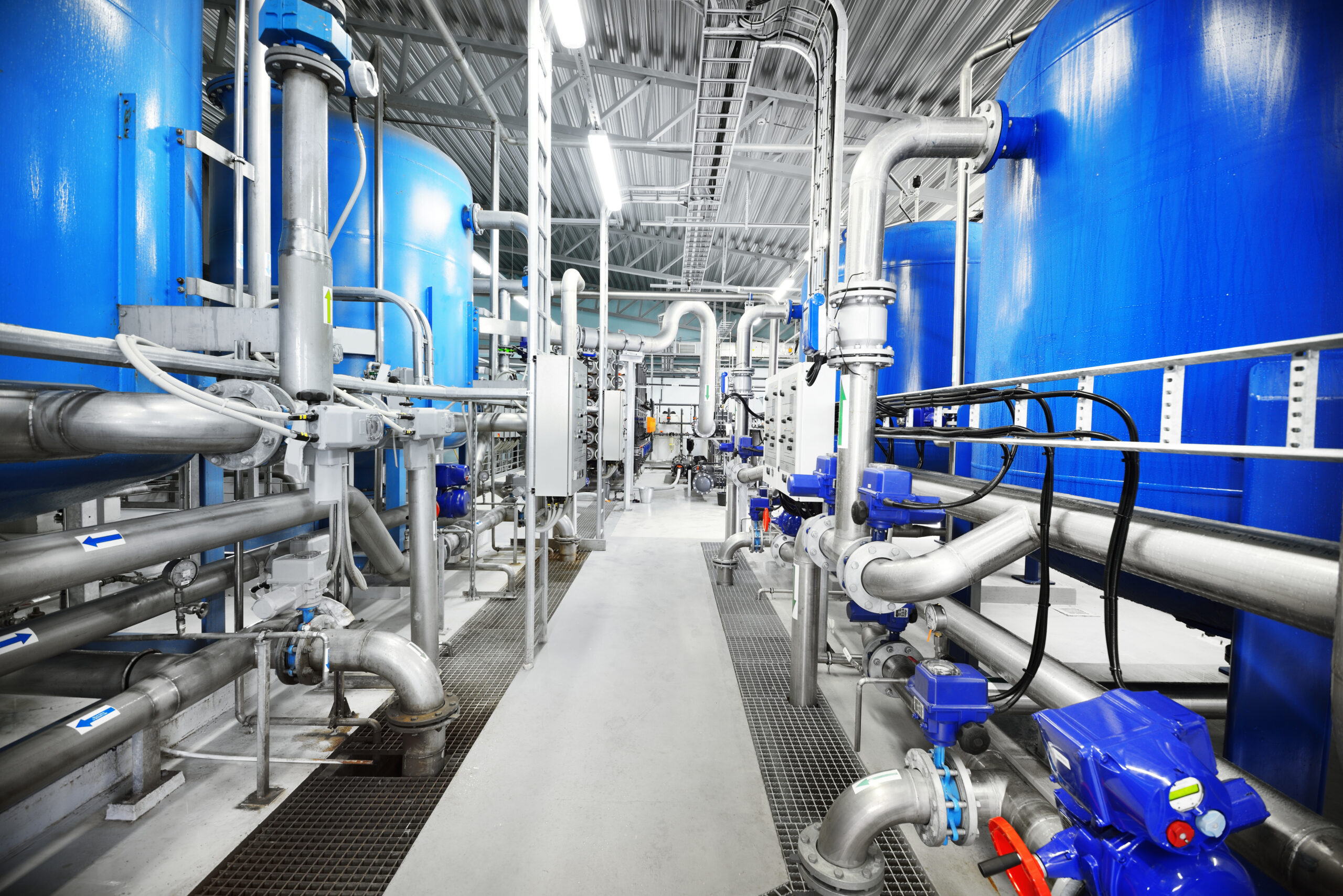
A drinking water treatment plant needed per- and polyfluoroalkyl substances (PFAS) treatment for domestic water, so the plant hired an engineering team to design a building for the granular activated carbon vessels to treat the PFAS. The plumbing needs for this building include a bathroom with a shower, wall-hung flushometer water closet, wall-hung lavatory and a laboratory sink for the chemical area.
At the domestic water entrance of the building, pressure loss through the water meter is 10 pounds per square inch (psi), the pressure loss through the pressure-reducing valve (PRV) is 5 psi and the pressure loss through the backflow preventer is 9 psi. The incoming water pressure before the water meter is 65 psi and the most hydraulically remote fixture is the wall-hung water closet, which is 200 feet from the domestic water entrance to the building and has a required pressure of 20 psi, as found in Table 604.3 of the International Plumbing Code (IPC).
All plumbing equipment is on the same floor as the water entrance, so no friction head loss needs to be calculated from the change in elevation. The equivalent length of the piping to the most remote fixture (including equivalent lengths for fittings) is 250 feet.
Design calculations
To start the design for the drinking water system, the engineer evaluated the water supply fixture unit (WSFU) totals for bathroom fixtures, referring to IPC Appendix E Table E103.3(2) for WSFUs. The total WSFUs for plumbing fixtures are as follows: two for the lavatory, 10 for the water closet, four for the showerhead and four for the laboratory sink, for a total of 20 WSFUs for the domestic water system.
Next, the engineer referred to IPC Appendix E Table E103.3(3) to estimate the demand load in gallons per minute (gpm). Because the only bathroom in the building has a flushometer valve for the water closet, the engineer estimated the demand load from the flushometer valve columns in Table E103.3(3). From the table, 20 WSFUs corresponds to 35 gpm. For domestic cold water at 35 gpm, the main could be sized at 1.5 inches because the velocity for water through Type L copper is roughly 6.5 feet per second (fps). Although possible, this exceeds the 4 to 6 fps rule of thumb for water velocity in a domestic water system.
The engineer decided to increase the pipe size to 2 inches and check the pressure losses in 200 feet of pipe to the bathroom where the most remote fixture is located. Upsizing the pipe to 2 inches will reduce pressure loss in the pipe along with the velocity. For Type L copper, a 2-inch pipe at 35 gpm will result in a velocity of 3.66 fps. While this is a little slower than the 4 to 6 psi rule of thumb, there will be no potential noise issue.
The bathroom is 200 feet from the domestic water entrance in the building. To calculate the pressure loss in the pipe per 100 feet, the engineer first calculated the equivalent length of pipe by multiplying 200 feet by 1.5. The engineer still needs to calculate the pressure available to overcome pipe losses before completing the calculation for average pressure drop per 100 feet of pipe. To do this, the engineer subtracted the pressure loss from the water meter, PRV, backflow preventer and most remote fixture. The available pressure is 21 psi. With that information, the engineer estimated the average pressure drop per 100 feet of pipe to be 7 psi.
The engineer has now determined that the equivalent length of piping to the farthest fixture is 250 feet; 250 multiplied by 7 psi per 100 feet is equal to 17.5 psi. With 3.5 psi still left for allowable pressure in the system, the drinking water and domestic water system have been sized properly.