New electrical systems included a vault upgrade, updated cables and generators to support modern electrical needs.
Learning objectives
- Understand how the Detroit Institute of Arts upgraded its electrical infrastructure from an obsolete 4.8 kV service to a modern 13.2 kV utility system.
- Learn about the design challenges involved in replacing aging transformer vault equipment, routing new medium-voltage cabling and selecting code-compliant transformer solutions for a historic building.
- Examine how the project improved electrical reliability, fire pump service, emergency power capacity and overall safety while minimizing disruption to museum operations.
Electrical system insights
- The Detroit Institute of Arts modernized its electrical system by replacing obsolete 4.8 kV utility infrastructure with a new 13.2 kV service, new switchgear, upgraded transformer vaults and a more resilient fire pump and generator arrangement.
- The project improved the museum’s electrical system through safer equipment, better power quality, code-compliant fire protection and carefully phased construction that minimized disruption while protecting staff, visitors and the art collection.
The Detroit Institute of Arts (DIA) is a historic institution located in Detroit’s cultural district. This museum has a rich history dating back to its founding in 1885. Established to promote the arts and culture in Detroit, the museum has grown into one of the largest and most significant art collections in the United States. Its original collection began with a donation of paintings and sculptures and over the years, the DIA has expanded to include more than 65,000 works, spanning a diverse array of cultures and time periods. The museum contains more than 140 galleries, an auditorium, an art reference library, art conservation department and a lecture hall, totaling approximately 658,000 square feet.
The DIA engaged SmithGroup to provide engineering services to upgrade and modernize the electrical services to the museum. At the time of the project initiation the cultural district was still operating on the infrastructure of the now-defunct Public Lighting Department (PLD) of Detroit.
PLD, once a vital municipal entity, faced decline due to a combination of financial troubles, aging infrastructure and the broader economic challenges facing the city. Established in the early 20th century, the PLD was responsible for providing street lighting and power to residents and businesses.
However, by the late 20th century, the department struggled with budget deficits and operational inefficiencies. Ultimately, in 2013, the department was dissolved as part of a larger restructuring effort during Detroit’s bankruptcy proceedings, with its responsibilities transferred to a large regional utility company. This shift marked the end of an era for Detroit’s public power services, reflecting the city’s broader challenges and the need for modernization in its utility management.
Electrical system service entrance
Upgrading the electrical systems of the DIA was a multipart project that consisted of upgrading equipment both inside the museum as well as outdoors at the electrical service entrance to the campus. The existing electrical services entered the site from underground manholes containing the utility’s 4.8 kilovolt (kV) circuits. Incoming 4.8 kV utility services used three-conductor medium-voltage cables routed into the building through underground duct banks.
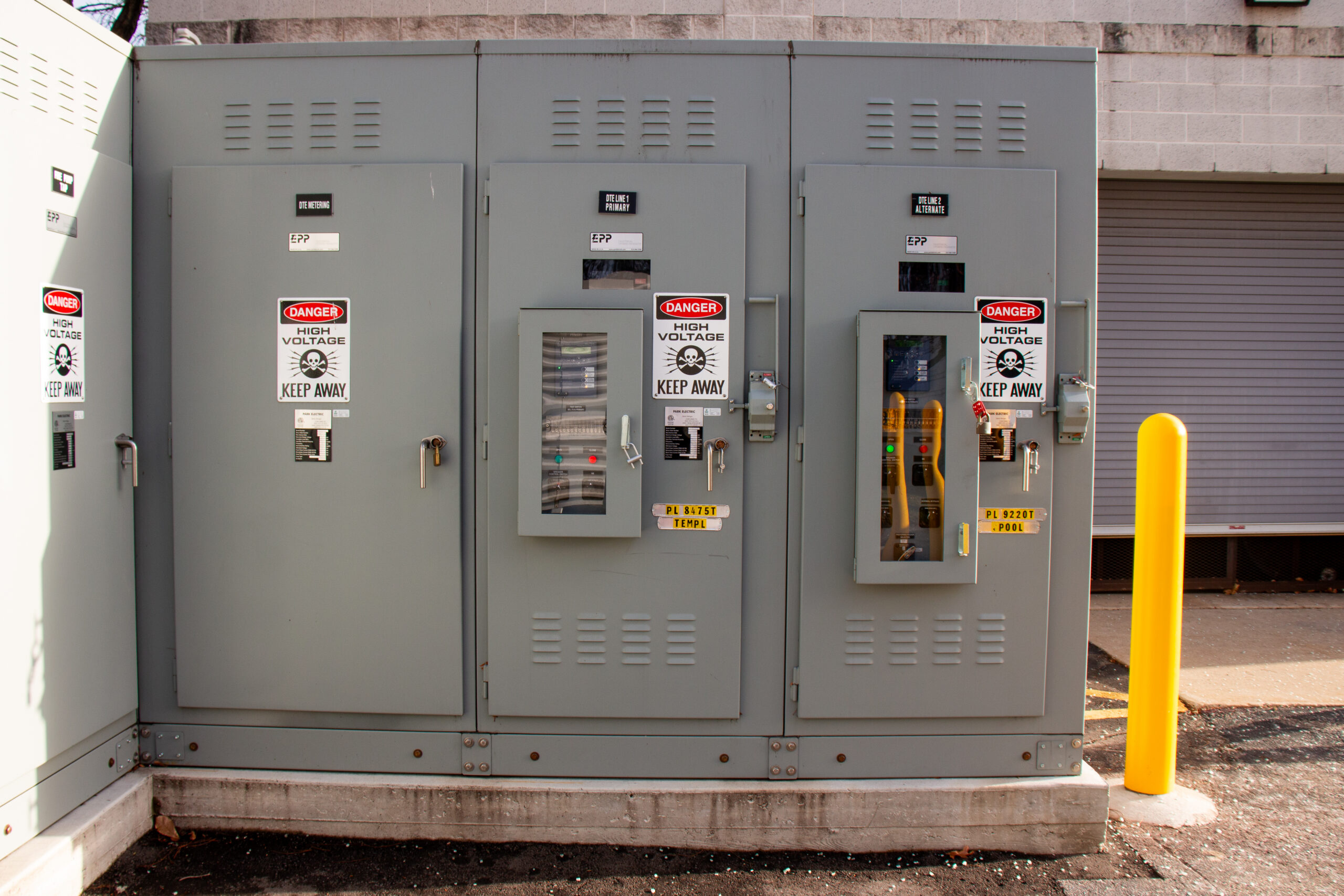
The most common distribution system used by the local utility company for serving its customers is 13.2 Y/7.6 kV. To connect into the utility’s 13.2 kV system, new 15 kV cables were brought from an underground manhole system which was totally independent from the existing 4.8 kV system. New exterior 15 kV class medium-voltage switchgear was required to accept the new 13.2 kV services provided by the utility. The incoming sections of the switchgear consisted of electronically interlocked vacuum circuit breakers (see Figure 1), which normally operated on one of the two 13.2 kV circuits, but can automatically switch to the alternate service upon loss of power.
New 15 kV cabling was routed from the new switchgear lineup to each of the existing transformer vaults located in the basement of the museum. Initially the intent of the engineering team was to use the existing pathways to route new 15 kV medium-voltage cable into the existing vaults, however upon further investigation it was discovered that the underground conduits were totally collapsed. The existing 4.8 kV cables were operating in the collapsed ducts, however it became clear that these pathways were not in suitable condition to be re-used for new cabling.
Screen wall to conceal electrical systems
While engineers may not mind looking at switchgear lineups, it turns out that the public does not find the grey boxes quite as appealing. The new switchgear lineup presented an opportunity to design a screen wall, which discreetly conceals the switchgear equipment while blending function with aesthetic appeal (see Figure 2).
The final design was selected through a collaborative effort with the DIA core leadership team. Initial design concepts were explored in various workshops with the core team. The chosen design honors the campus’s history by offering a modern interpretation of the original architecture and incorporating DIA branding.
Crafted from durable, weather-resistant materials, the screen wall is built to withstand the elements. It features two vertical planes: the outward-facing plane is made of perforated aluminum, while the inner plane consists of a galvanized B-deck, supported by galvanized steel tubes.
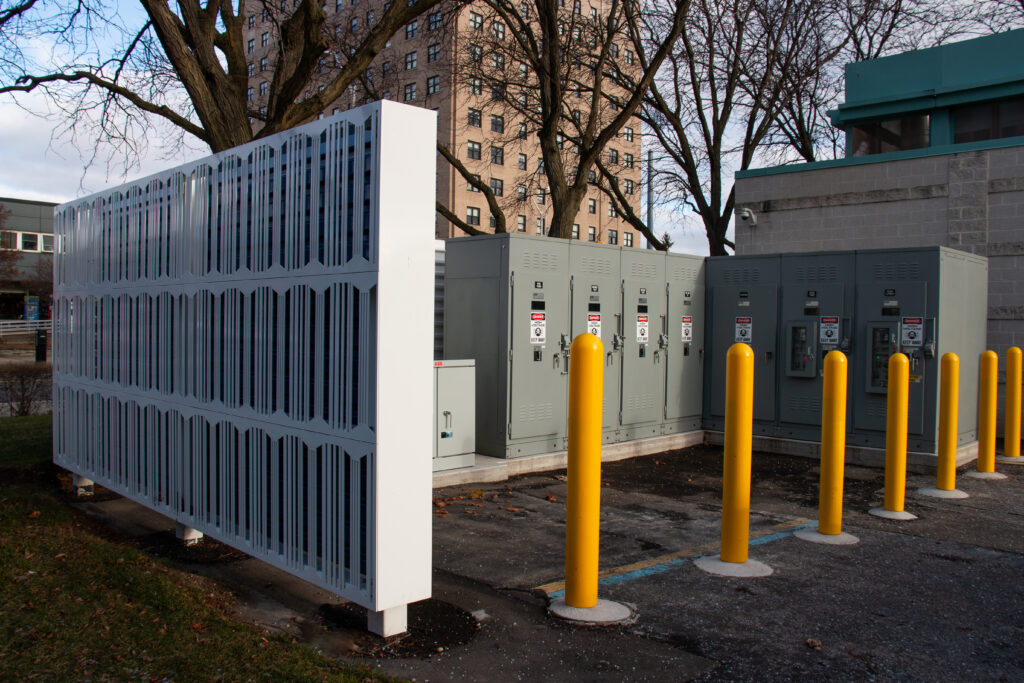
The screen wall design includes a perforated pattern of the DIA logo, powder-coated glossy white, transforming it from a functional element into an appealing focal point. The second plane, painted in DIA’s signature blue, enhances visual appeal by creating a backdrop that adds depth and interacts with natural daylight.
Existing electrical vault conditions
The existing conditions of the electrical rooms presented the design team with some challenges as well as opportunities. The rooms were built as “transformer vaults” in the true sense of the words as defined by NFPA 70: National Electrical Code (NEC) Article 450, which requires these spaces to have three-hour fire rated construction and sills for oil containment among other requirements. Transformer vaults such as these were typical for mid-20th century buildings in Detroit, as the local utility company typically would install its mineral oil transformers in the vaults to step down the incoming 4,800 V service to the building’s utilization voltage. These rooms were only accessible to utility company personnel.
The existing transformers were single-phase “can” style transformers that we would typically expect to see mounted high on utility poles in modern applications. To provide three-phase service to the building, three of these single-phase transformers were connected to each other in a delta or wye configuration using exposed cables and terminations.
The other main pieces of equipment found in the existing vaults were oil-insulated medium voltage circuit breakers. These circuit breakers provided a means for the utility to disconnect the transformers and provide overcurrent protection using analog relays. Current transformers were installed on the line side of each switch for metering the power usage on each incoming 4,800 V service.
When evaluating equipment that is 50 years old or greater, it is important to consider the possibility that hazardous materials may be present, as some of the systems may have been installed in a time where the knowledge of the effects of certain materials and chemicals was not yet known.
For this project, the main concerns that were evaluated were whether the insulating oils contained polychlorinated biphenyls (PCBs) and whether the medium-voltage cable outer layer contained asbestos. No PCBs were found in the oil; however, the medium-voltage cables did contain asbestos, requiring specific remediation processes to be followed to properly decommission the cables.
Electrical vault design solutions
Due to the existing conditions, the engineering team was presented with several design challenges to solve.
Topping the list of design constraints was the physical space available for the new electrical equipment in the vaults. The weight and size constraints were not an issue previously because the utility used individual single-phase transformers; however, that was not an option for the new equipment due to the safety hazard associated with open terminations.
Traditionally, when bringing medium-voltage feeders inside a building, engineers use unit substations to step down the voltage to the building equipment’s utilization voltage. Unit substations typically consist of a section of medium-voltage metal-enclosed switchgear with a load break switch close coupled to a medium-voltage transformer. Dry-type transformers are often specified in indoor applications, however liquid-type transformers are being specified more often now due to the available of less-flammable insulating fluids.
Standard unit substation designs presented a multitude of problems when being considered for this application. First, the amount of floor space required was far greater than was available, especially when considering that ideally this equipment would be installed in phases. A standard 15 kV metal-enclosed load break switch is 3 feet wide and 7 feet tall, while a substation style medium-voltage transformer is 8 feet wide by 9 feet tall. These dimensions were a nonstarter due to the limited floor space and the height of the transformer enclosure.
Another issue that became apparent was the weight of a dry-type substation transformer; the largest size required for the project weighs approximately 15,000 pounds, which exceeded the building’s elevator capacity by 5,000 pounds.
The mounting design constraints with dry-type substation transformers led the engineering team to investigate liquid-filled transformer solutions. Liquid-filled transformers are available in indoor substation style configurations, however the dimensions of those were not much of an improvement over the dry-types. Liquid-filled transformers also allow the transformers to be made lighter temporarily by draining the fluid and reinstalling after the unit is set in place; this strategy allowed the transformers to be transported down the 10,000 pounds. elevator without exceeding the capacity.
Pad-mount style transformers offer the most compact footprint when comparing them against their counterparts of the same kVA rating, so the decision was made to use pad-mount transformers for the project. Pad-mount transformers can offer even further flexibility in fitting through tight openings, as some can be specified with a removable termination cabinet and removable radiator fins.
As an additional benefit, liquid-filled transformers enjoy a small bump in efficiency over their dry-type counterparts and the liquid can be sampled in the future as a preventive maintenance diagnostic tool.
Pad-mount transformers are available with standard mineral oil or less-flammable insulating fluids. It would have been code compliant to reinstall mineral oil transformers inside of the existing spaces, as they were constructed as three-hour fire rated transformer vaults, however it was determined that the less-flammable insulating fluid was the optimal solution. The engineering team was confident that the small cost adder associated with less flammable fluid was worth it to give the museum’s staff, visitors and artwork the best possible protection against fires.
In addition to the previously mentioned advantages, liquid-filled pad-mount transformers also have the benefit of being able to use their insulating oil to provide disconnecting means and overcurrent protection without any additional external equipment. This feature was a great benefit to the project, as it enabled each transformer to have its own integral load-break switch and fusing.
The integral disconnecting means and overcurrent protection was an important design feature, as it enabled the use of a single medium voltage feeder to be daisy-chained between multiple transformers without the need for additional medium voltage switchgear.
Fire pump electrical system considerations
The electrical upgrades project presented an opportunity for the DIA to also upgrade how its existing fire pump power feed was designed. The existing fire pump was served from a tap off the secondary of one of the 480 V service transformers that would be de-commissioned as part of the scope of work. At the time this was installed, the installation was considered code compliant, as the transformers were owned by the utility company and the tap was made before the downstream service disconnecting means.
However, after completion of the upgrades, this existing configuration of the fire pump power source would not be compliant with NEC 695.3(A), which requires that the fire pump be supplied from a connection located ahead of the service disconnecting means. The new system’s design incorporated a dedicated fire pump tap from the main service switchgear, which then fed a dedicated fire pump disconnecting means and fire pump transformer. The fire pump transformer stepped down the new 13.2 kV service voltage to 480 V to match the voltage of the existing pump.
Generator system upgrades
During the normal power upgrades project, the DIA also decided that its emergency power generator system was in need to modernization. The existing generator was a small 208 Y/120 V generator that was supporting a few select loads such as some security related loads and refrigeration equipment. As is common with most facilities with critical loads, their need for generator capacity expanded over time and it became apparent that additional generator capacity was required.
In addition to expanded data and security loads, the DIA wanted to provide additional resilience to the fire pump system. Although there was now an upgraded fire pump service, the fire pump would still be served from a single power source, which is permitted if the source is considered reliable.
However, even with a reliable utility source, the DIA recognized that the fire pump was a critical part of protecting the museum’s collection against fire loss and increasing fire pump system reliability was a sound investment.
Because the existing generator was 208 Y/120 V and the fire pump was 480 V, it became clear that the best solution for the generator upgrades was to provide a 480 Y/277 V generator sized to handle the fire pump load and provide a step-down transformer to serve all of the 208 Y/120 V loads. A new automatic transfer switch, transformers and panelboards were also integrated into the design to provide a completely upgraded emergency power system.
The typical method of providing two sources of power to a fire pump is to use a fire pump controller with an integrated automatic transfer switch. Fortunately, the DIA had the foresight to install this type of controller years before when the fire pump was installed. This streamlined the fire pump power upgrade process significantly; the installing contractor simply had to land the new generator power and control conductors in the controller.
Construction process and temporary services
The switchover process to migrate from the existing equipment to the new was a very detailed and precisely planned process that required close coordination between the DIA, the installing contractor, the engineering team and the utility. Most switchover work was performed on days that the museum was closed to the public to minimize the disruption to the museum’s operations and its patrons.
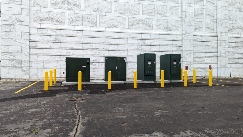
Temporary outdoor pad-mount switches and transformers (see Figure 3) were installed by the utility company; the transformers provided 480 Y/277 V and 208 Y/120 V service directly to existing switchboards, which then permitted the existing 4.8 kV equipment to be decommissioned and removed. This temporary equipment was key in minimizing the amount of downtime needed to perform the switchover when taking the old equipment offline.
Additional electrical system scope
The DIA recognized that the electrical equipment was not the only thing that needed to be upgraded in the electrical vaults. The mechanical systems, sprinkler systems, doors, lighting and paint were all upgraded provide a safe, comfortable space for the facilities staff and maintenance technicians.
One unexpected challenge that arose from installing modern energy-efficient transformers was that there was no longer enough waste heat being generated by transformer losses to adequately heat the electrical vaults during the winter months. Electric unit heaters were installed to supplement the transformer heat loss and keep the vaults at an appropriate minimum temperature.
Completion of electrical system upgrades
Upon the completion of the new electrical equipment installation, the improvements were immediately visible to the DIA facilities team. The new utility services exhibited none of the previous symptoms of poor power quality, allowing the DIA to operate more efficiently and reduce the burden on its staff. Another observable benefit upon completion was the improved safety of the electrical systems in the vaults as all cabling was installed in conduit, leaving no exposed live parts.
The DIA continues to stand as a testament to the city’s rich cultural heritage and artistic legacy. The transformation of its electrical systems reflects not only the museum’s commitment to preserving art but also to adapting to modern technological demands. The engineering challenges faced were met with solutions emphasizing safety, efficiency and protecting the museum’s collection. By embracing advancements in electrical infrastructure, the DIA ensures that it can continue to serve the community and protect its invaluable collections for generations to come.