Modular six-pipe heat recovery chillers expand a typical chiller’s ability to provide simultaneous heating and cooling by adding a third “source” loop.
Learning objectives
- Understand modular chillers and how they can be used in heat recovery applications.
- Learn how modular six-pipe heat recovery chillers can be used in simultaneous heating and cooling applications.
- Apply engineering principles to heat recovery chillers to integrate them into a building hydronic heating and cooling system.
Chiller insights
- This article explains how the modular six-pipe heat recovery chiller can lower building EUI by delivering simultaneous heating and cooling while using a third source loop to balance mismatched loads.
- It also emphasizes that successful heat recovery chiller design depends on careful attention to flow, system volume, piping layout and controls so the chiller operates efficiently and avoids lockouts.
Lowering energy use intensity (EUI) is essential in the built environment, as rising cooling demands, escalating energy costs and increasing expectations for high-performing, sustainable buildings make efficiency more critical than ever. Implementing a combination of energy conservation measures — such as heating, ventilation and air conditioning (HVAC) optimization, lighting retrofits, smart building automation and building envelope upgrades — can help to reduce energy consumption.

Heat pumps and heat recovery chillers (HRCs) can be highly effective instruments for electrifying heating systems in a building and, in turn, reducing a building’s EUI.
Whether driven by owner or energy code goals (i.e., 2024 International Energy Conservation Code C403.11.6 requires healthcare facilities to provide heat pump chillers where heating water is provided by the facility), or by code requirements to electrify, there has been greater adoption of these cooling/heating devices as more central elements in building and central plant designs. This leads to continued innovation and change in the available equipment and in how engineers design systems to serve larger and more complex facilities.
Modular heat pumps and HRCs are prime examples of equipment engineered to maximize efficiency. They provide simultaneous heating and cooling and “check the box” as a means of electric-sourced heating in fully electrified central plants.
The way heat pumps and HRCs are typically applied is to use energy modeling to estimate the simultaneous heating and cooling load in the building. After loads are calculated, a modular four-pipe HRC sized for similar load capacity is selected. Because capacity is being generated simultaneously by central equipment, the remaining load can be met by other primary equipment that is considered less sustainable (e.g., low energy efficiency ratio, low coefficient of performance, fossil fuel usage).
Modular six-pipe HRCs build on the four-pipe chiller concept and can balance the generation of chilled and hot water while using a third loop as a heat sink/source when the building’s hot and chilled water loads are not adequately balanced. This allows for load “expansion.” Where four-pipe models were limited to simultaneous heating and cooling, six-pipe models can now combine simultaneous loads with naturally occurring sources to maximize heat rejection or generation.
Modular six-pipe heat recovery chillers
In buildings where there is demand for simultaneous heating and cooling, such as commonly found in hospital and laboratory facilities, modular six-pipe HRCs use chilled water generation and hot water reject-heat to help satisfy the building’s overall heating and cooling demand. During periods when hot water demand exceeds chilled water demand, a six-pipe HRC will use a “source” loop to reject excess cooling to a source, essentially sending that cool water out to be warmed up. That source could be a geothermal field, exhaust heat recovery coils, or any other natural or consistent heat source.
The inverse is also true. During periods when chilled water demand exceeds hot water demand, excess heat can be rejected to the source.
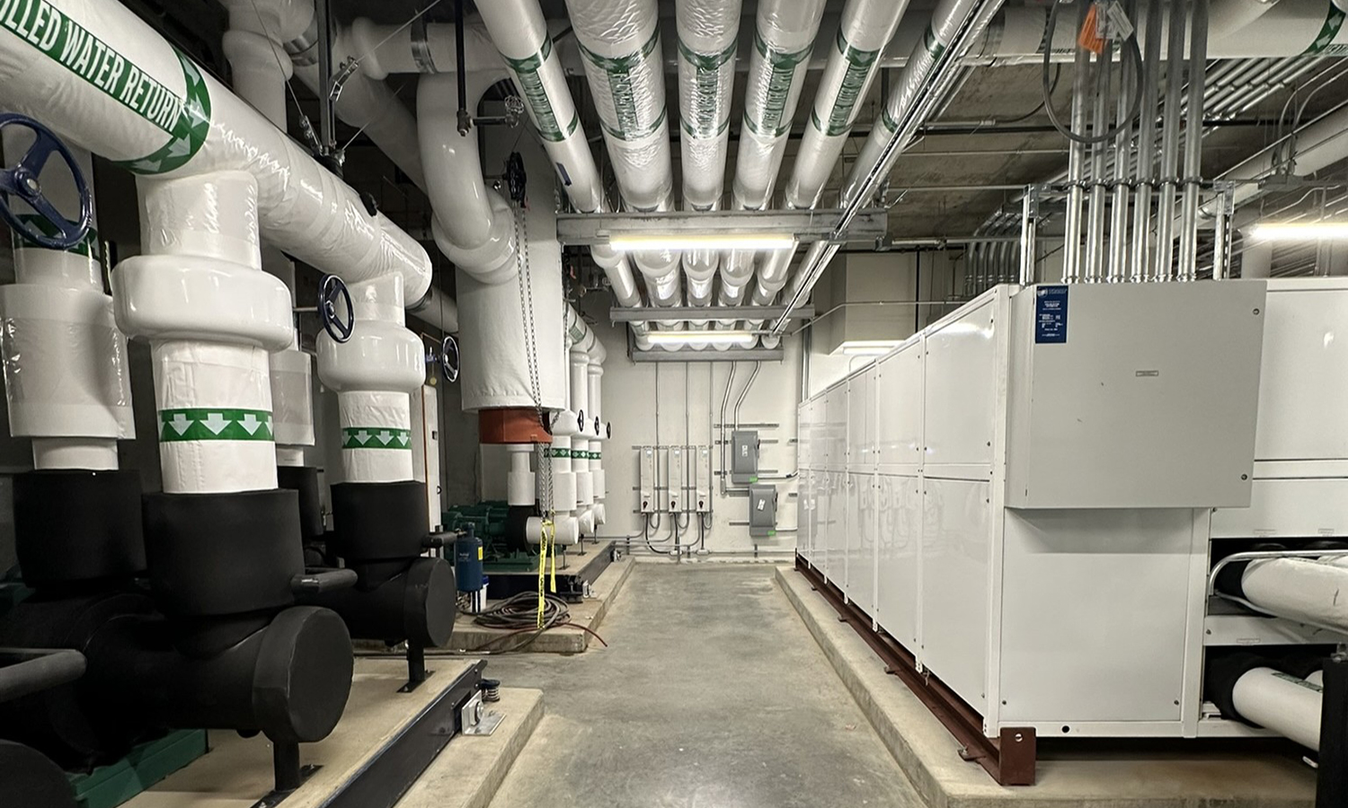
Modular six-pipe HRCs typically consist of multiple self-contained units with scroll compressors (typically two per module) linked together into a “bank.” The bank has a master control panel that controls the number of operating modules. The panel also controls whether the modules and bank operate in simultaneous heating and cooling or reject hot or chilled water to a geothermal field.
Modular six-pipe HRCs come in a few different styles. Some use liquid in all three loops to maximize heating and cooling efficiency. Some types separate all three loops, while others blend water between the loops. Then there are those that only use liquid in two loops and use refrigerant in air-cooled condensers as a “source.” The latter is typically referred to as a heat recovery air-source heat pump.
The leading chiller manufacturers initially developed six-pipe units and their piping/valving configurations for geothermal systems to maximize potential for simultaneous heating and cooling while allowing for the geo-field (source) to balance any overall heating/cooling load imbalance. This enables the activation of the installed capacity of the equipment, better leveraging the capital investment in the HRCs.
Geothermal fields often have cost, schedule, and/or area limitations. As a result, an increasing number of projects in the industry are leveraging exhaust air streams or other source opportunities, such as large sewer pipes, as alternatives. For more load-intensive facilities like hospitals and labs, these “sources” reach their heat-rejection/extraction capacity.
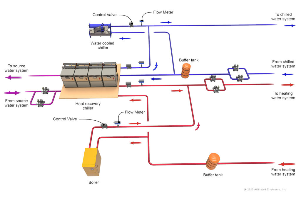
Typically, the design heating and cooling demand of the building will exceed the maximum load the HRC can provide. This requires integrating the HRC into systems that include heat pumps, boilers, steam-to-hot-water converters, air- or water-cooled chillers, campus district energy heat exchangers or other primary heating and cooling equipment.
Chiller flow, temperature considerations
Any small modular chiller has important flow and temperature guidelines to consider during design. Modular six-pipe HRCs are no exception. Given the increased dynamic nature of the systems where these machines are applied and the delicate balance that they prefer, it is even more important to give attention to the following:
- Flow: Too little flow can cause freeze lockouts or high refrigerant pressure lockouts. Too much flow will oversaturate the heat exchangers, causing the water temperature to drift away from the setpoint. Many manufacturers will use flow switches to ensure adequate flow in each module to protect the compressors.
- System volume: Modules and compressors in a six-pipe HRC will stage up and stage down to provide more capacity based on their leaving water temperature separation from the setpoint. Each module doesn’t have much volume, so the system piping needs to compensate. Sudden temperature swings can cause a rapid stage-up of operating modules, resulting in freeze lockouts as an unintended consequence. A buffer tank may be provided to add water volume to the system to ensure adequate cycle time and to prevent short cycling.
System piping layouts
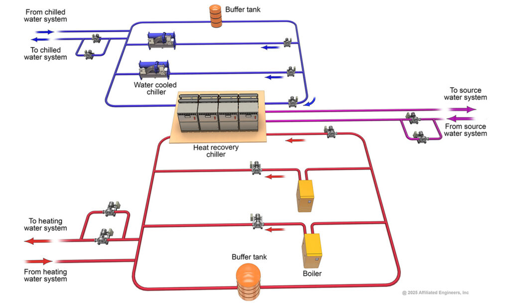
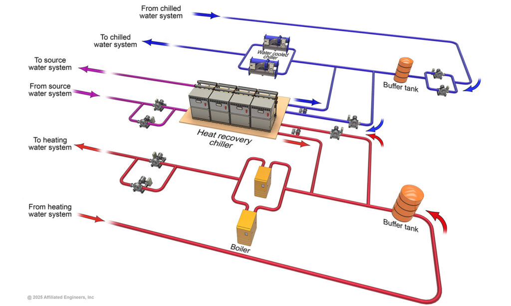
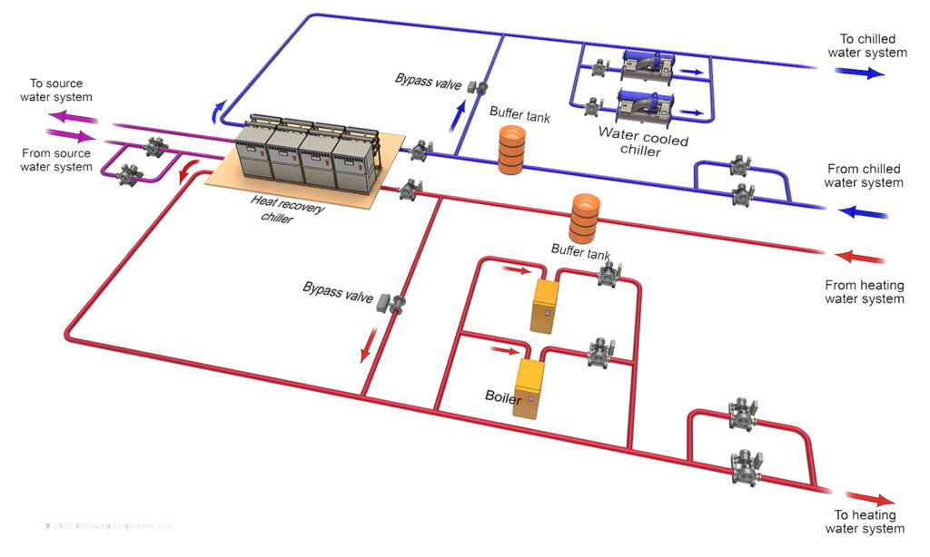
Piping layouts are a design parameter that needs to be considered in any hydronic system. How the HRC ties into each heating and cooling system on a particular project is an important decision to ensure adequate flow and system volume is provided. Whether the HRC should be used as the leading capacity source or as a supplemental strategy for efficiency will also influence how it is integrated into each system.
- Variable primary: This piping layout is considered industry standard for buildings with high-efficiency goals and large central plants because it maximizes pump energy savings. Because the entire building’s flow runs through one set of pumps, the balance of the central plant and how it is effectively used by the building should be carefully evaluated, especially under low-load conditions (see Figure 2).
- Primary/secondary: Each primary piece of equipment is individually pumped, which helps to simplify the controls for ensuring adequate flow at each piece of equipment. System volume in the primary loop should be carefully evaluated to ensure water temperature doesn’t short-cycle too quickly (see Figure 3).
- HRC in sidecar: The HRC is separated from the main piping system, with supply and return piping to the HRC tied into the return pipe of the main system. The HRC is used to trim the return water temperature to the other primary equipment. This can lead to low entering water temperatures at the downstream equipment when the downstream equipment first stages on, which results in low lift at the primary equipment (see Figure 4).
- Primary equipment in sidecar: The main system piping prioritizes the HRC. The HRC bypass is used to bypass water around the HRC, while the other primary equipment in sidecar is used to cover the gap to the setpoint. Note that HRC-integral bypass valves would likely be insufficient for the bypass flow required for this configuration (see Figure 5).
Ancillary design considerations
Outside of the two main guiding principles, flow and system volume, consider these other design guidelines when implementing six-pipe HRCs in a hydronic system.
Module stage-up and stage-down: Different manufacturers will use different stage-up and stage-down setpoints. How this is controlled can make the design susceptible to freeze lockouts or high refrigerant pressure lockouts, especially during low-load conditions. Design engineers should work with the chiller manufacturer during the design phase to determine how to use the overall system controls to help supplement the HRC packaged controller to operate more resiliently.
As mentioned, HRCs can be highly reactive to swings in system water temperature. As banks bring on an additional module, it can insert a larger influx of cooling into the system. Some manufacturers offer variable frequency drives (VFDs) on compressors, which serve to more slowly raise/lower the water temperature when a compressor turns on. This helps prevent overcorrections to untempered water slugs and accidental freeze lockouts.
VFDs can also help bridge low-load conditions during overnight moderate temperatures or shoulder seasons. Conducting studies across different scenarios during design can confirm that peak- and low-load conditions can be satisfied by all equipment, including HRCs, pumps, terminal equipment demand and control valve turndown.
HRC pumps: HRC selections are typically provided with a flow requirement for the bank of modules. As the chiller brings on and takes off modules, the flow requirement changes and is determined by dividing the total bank flow by the number of operating modules. Pumps can then be controlled to provide the flow required per module or the required differential pressure at the chiller header, as required by the manufacturer’s selection data.
Although pumps can be an effective means of providing flow to the HRC, they are not always applicable due to the system layout (i.e., in variable primary piping configuration; see Figure 2). In that case, control valves and/or flow meters that direct and balance flow to each piece of primary equipment throughout the central plant can be used instead.
System fluid mixing: Be conscious of water chemistry and how systems are or are not separated within the HRC. Some manufacturers use three-way valves to bypass water to the source loop or intermediate valve staging packages that mix water off a four-pipe header. This could lead to mixing of water chemistry, meaning if glycol is used in one of the HRC loops, it will be diluted or contaminated by another loop’s water.