Safety is the key component of all electrical power systems and must be included in the design — and maintained through the electrical system’s life
Learning Objectives
- Identify applicable codes and standards that govern the safety of electrical systems.
- Learn about best practices to incorporate into electrical system design to enhance safety.
- Understand the safety impacts of proper electrical system maintenance.
Electrical safety insights
- There are several ways for electrical engineers to design electrical systems to meet the safety requirements set forth in codes and standards.
 Understanding the various arc flash mitigation techniques goes a long way toward ensuring personnel safety.
It is always the responsibility of end users to practice safety when working with electrical systems. However, design engineers are also responsible for ensuring electrical systems are designed with safety in mind.
Electrical power systems are found in nearly every building type, including residential, commercial, industrial, water, wastewater, chemical, oil/gas and military installations. While all electrical systems share the same basic principles and corresponding safety features, the requirements of each system depend on its specific application.
It is the duty of the design engineer to ensure that all applicable codes, standards and requirements are implemented and to examine each system in detail and ensure that the system is designed with safety in mind.
Electrical safety codes and standards
It is the design engineer’s responsibility to perform code analysis and to identify all codes and standards applicable to their projects, including those adopted by the local authority having jurisdiction, the state and any applicable federal requirements. Electrical design and installation requirements to minimize electrical hazards are defined by NFPA 70: National Electrical Code. A wide variety of other standards also govern the design of electrical systems. A holistic approach must be taken where all aspects of the design are considered, including its location, application, surrounding environment, any hazards that may be present and the intended end use.
Some codes, standards, guidelines and references that may be relevant to many designs include:
- ANSI/NETA MTS: Standard for Maintenance Testing Specifications for Electrical Power Equipment and Systems
- International Building Code
- International Fire Code
- International Mechanical Code
- Institute of Electrical and Electronics Engineers
- National Electrical Manufacturers Association
- NFPA 1: Fire Code
- NFPA 70: National Electrical Code
- NFPA 70B: Recommended Practice for Electrical Equipment Maintenance
- NFPA 70E: Standard for Electrical Safety in the Workplace
- NFPA 72: Fire Alarm and Signaling Code
- NFPA 101: Life Safety Code
- NFPA 110: Standard for Emergency and Standby Power Systems
- NFPA 780: Standard for the Installation of Lightning Protection Systems
- NFPA 820: Standard for Fire Protection in Wastewater Treatment and Collection Facilities
- Occupational Safety and Health Administration
- Unified Facilities Criteria.
Electrical hazards
There are two main types of electrical hazards that end users are exposed to: shock hazards and arc flash hazards. Both hazards can cause severe injuries, fatalities, significant property damage or facility outages.
Shock hazards occur when an electric current flows through an unintended path, including through the human body. Depending on the voltage and current levels, shock hazards can cause severe injuries or fatalities and destroy equipment.
Arc flash hazards occur when a flowing electric current is interrupted and an arc is created. The arc is a flexible electric conductor between two parts of electrical equipment that ionizes the air. The temperature of the arc is very high, up 35,000°F, which is three times as high as the temperature of the surface of the sun. This high temperature is capable of causing second degree burns even without direct contact with the arc.
The high arc temperature may also cause an explosive expansion of the surrounding air and metal, which is called arc blast. The arc flash hazard at a particular location is measured as the “incident energy,” which is the energy per area (cal/cm2) that a worker would receive if an arc flash occurred. The incident energy is influenced by three main factors: the available fault current, the clearing time (the duration of the arc incident) and the distance of the worker’s body from the arc.
Safety during design
At a minimum, all projects must meet the applicable codes and standards, including NEC. However, these codes should be considered the bare minimum and do not always include design techniques or features that will ensure the safest and most reliable electrical system. Special care should be given to some design elements and the design engineer to consider if additional design features above and beyond the code-required minimum should be implemented. Some safety-related topics that should be evaluated include:
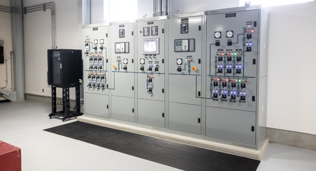
Distribution equipment bus configuration: The safest way to work on electrical equipment is to de-energize it. However, this would require an outage for equipment and/or customers served by the equipment. One solution to this issue is to design electrical distribution equipment in a double-ended main-tie-tie-main configuration (see Figure 1). This allows one complete side of the distribution equipment to be de-energized and worked on safely while maintaining facility operation through the other half of the distribution equipment provided downstream distribution equipment is also designed redundantly (fed from both sides of distribution equipment via an automatic transfer switch or with redundant equipment distributed between both sides of main-tie-tie-main equipment). Figure 1 shows a typical main-tie-tie-main bus configuration, which allows for one entire switchgear (including one tie breaker) to be de-energized for maintenance.

Working clearances and egress: The NEC defines minimum working clearances and egress requirements in Article 110. However, these clearances do not always allow for easy and safe maintenance of the electrical equipment. For example, 480-volt switchgear with removeable circuit breakers requires a minimum of 3 feet of clearance if no live or grounded parts are located at the edge of the working space.
However, this is likely not enough clearance to allow an electrician to remove a breaker easily and safely from a switchgear cubicle. Additional space should be considered for safety and ease of electrical maintenance and egress from the working space. See Figure 2 for an example of an electrical room designed with additional space to allow for the ease of maintenance.

Accessibility of equipment: Most electrical equipment will need to be maintained or replaced at some point in the future. Special consideration for how this work will be performed should be given during design. For example, doors or hatches installed in the building must be large enough to allow equipment to be removed if required. Equipment that is difficult to access, such as generators, may need a platform or additional access to facilitate in-place maintenance.
In other instances where equipment is mounted more than 8 feet above the finished floor, consideration should be given to provide remote operation means at working level. For example, motorized valves may require remote control stations located at operator’s level if the valve is mounted near the ceiling.
Equipment ratings and compatibility with installation area and chemicals: It is critical that equipment maintains its integrity throughout its useful life. This means that the equipment must be rated appropriately for the conditions it is installed in.
NEMA defines enclosure ingress ratings, which define a degree of protection to personnel against incidental contact with the enclosed equipment and how water and dust tight and corrosion-resistant the enclosure is. If there is any chance of nonrainwater spray, it may be beneficial to select a NEMA 4 or NEMA 4X (improved corrosion resistance) enclosure. This is in addition to ensuring that equipment installed in hazardous locations meets the requirements of NEC Chapter 5 and any other applicable NFPA codes.
Hazardous locations (also sometimes called classified locations) are locations that ignitable/explosive concentrations of flammable gases, combustible liquid vapors, combustible dusts and/or flying fibers are present or may be present in. In addition to specific area requirements, generally conduits entering and existing classified areas are required to be sealed off to prevent the migration of hazardous materials through the conduit.
Additionally, the equipment materials, including enclosures, conduit, mounting hardware or other items must be selected to be compatible with the environment. For example, outdoor enclosures near saltwater bodies may benefit from being specified as 316L stainless steel as opposed to the more common 304 stainless steel or galvanized steel. Special care should also be given if the materials will be exposed to any process chemicals. For example, steel (including stainless steel) and aluminum should not be used in areas with chlorine or sodium hypochlorite. This is because the chlorine can rapidly degrade the enclosures and compromise their integrity, creating a safety hazard.
Harmonic mitigation: Harmonics can have many negative effects in electrical systems including overheating of conductors and transformers as well as nuisance tripping of circuit breakers. The engineer must evaluate if the system includes a large quantity of nonlinear loads such as variable frequency drives, uninterruptible power supplies and computers. If the system has a significant nonlinear load, a harmonic evaluation or study should be performed.
IEEE 519 defines recommended limits for harmonic distortion in electrical power systems. If the study indicates harmonics are above IEEE 519 recommended limits, harmonic mitigation should be implemented in the electrical system and equipment. Although IEEE 519 may be applied considering the utility service as the “point of common coupling,” it is often better to mitigate harmonics closer to the source and to instead evaluate the point of common coupling to be either the harmonic source device’s terminals or the next upstream distribution equipment. This can prevent harmonics and their negative impacts from spreading throughout the electrical system.
Fault current evaluation and limitation: During the design phase, the engineer should evaluate the available fault current in the proposed electrical system to ensure that the specified electrical equipment short-circuit interrupting and/or withstand ratings are selected appropriately.
High available fault currents are one of the main factors that contributes to high arc flash incident energies. Fault currents are primarily dictated by the rating of the transformer serving the electrical system. If sizing the transformer is the design engineer’s responsibility, limiting the size of the transformer and splitting the load across multiple transformers can decrease the available fault currents and limit the potential for high arc flash incident energies. For example, it is a best practice to avoid customer-owned transformers over 2,500 kilovolt-ampere at 480/277 V wherever possible.
Arc flash analysis: Arc flash analysis should be performed before energization of new electrical systems to determine the presence of arc flash hazards within the electrical system during a fault and to determine the appropriate safety precautions including personal protective equipment, which should be worn while working on energized electrical equipment. The design should consider various means of mitigating the arc flash in the electrical system during design.
Arc flash mitigation
Arc flash hazards are one of the most significant safety hazards for people working on electrical systems. It is largely difficult to control the available fault current and distance from a potential arc flash event. The primary way to lower the arc flash incident energy in an electrical system is to reduce the clearing time of protective devices upstream of the fault location, however this also works against the selective coordination of the electrical system, which aims to minimize outages during fault conditions and ensure the correct protective device interrupts a fault.
There are several methods to mitigate arc flash hazards:
Optical arc flash detection: This works by measuring the light intensity inside of electrical equipment using fiber optics and a special relay. If this relay detects a sudden flash of light and a corresponding sudden increase in current, it trips the breaker immediately and bypasses the time delay. This can end the arc flash event quickly and reduce the hazard. This approach is more applicable to large equipment such as switchgear and switchboards.
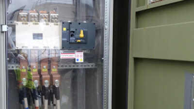
Arc-reducing maintenance switch: ARMS are typically installed on large distribution equipment such as switchgear and switchboards. When enabled, typically during maintenance activities, the ARMS switch allows the circuit breakers to trip instantaneously when a fault is detected. While this may compromise coordination, it will decrease the clearing time and reduce the arc flash hazard at that equipment. While the ARMS switch can reduce arc flash hazards, it cannot eliminate them entirely and the remaining hazard present (and corresponding appropriate PPE) when the switch is activated must be determined as part of the arc flash study.
Electronic trip units: A common location for high arc flash incident energy is on the secondary of low-voltage lighting-type transformers. This is because these transformers are often fed by thermal-magnetic type circuit breakers with limited or no adjustability. As the transformer limits the fault current on the secondary side, these breakers can take a long time to operate and clear a fault, leading to a very high incident energy level at the panelboard it is feeding. This can be mitigated by installing breakers with electronic trip units for the transformer primary feeders, as these trip units offer increased adjustability so that the breaker can trip faster in a secondary fault condition. Electronic trip breakers are also useful for limiting arc flash energy levels on low-voltage feeders greater than 250 amps that would be otherwise fed by thermal-magnetic circuit breakers.
Remote racking and operation of breakers: Arc flash events often occur because of component failure while parts are moving. While electrical distribution equipment is stationary most of the time, when breakers are opened/closed or racked in/out, their parts must move internally or travel within the equipment. This makes these operations some of the most likely to induce arc flash events.
The need for electricians to be in front of the equipment while operating can create a very dangerous scenario where even the best PPE cannot prevent injury or death. To mitigate this hazard, a mimic panel can be installed elsewhere in the electrical room. The mimic panel contains breaker control switches similar to the distribution equipment but at a remote location. If an arc flash event occurs, the electrician will be outside of the arc flash boundary. This allows for operation of circuit breakers safely and without the need for heavy and cumbersome PPE (see Figure 3).

As an additional step, switchgear and equipment with draw-out circuit breakers can often be specified with remote racking devices. These devices can be attached to the circuit breaker cubicle and then, via remote control, enable the circuit breaker to be racked in and out using an electric motor. This allows the electrician to be safely away from the equipment in case an arc flash event occurs during breaker movement.

Safety after installation
Maintenance: The key to safe and reliable electrical system is properly functioning equipment. All equipment will deteriorate with time, so it is essential that equipment is tested and maintained regularly to ensure that equipment is kept in proper condition. If equipment degrades it can lead to an immediate failure such as a short circuit or a more dangerous “hidden” failure that is only discovered when the equipment is most needed. These hidden failures can be very dangerous as they often present themselves at the worst possible moment, such as a breaker failing to open when needed to interrupt a fault or physically failing and causing an arc flash event.
The ANSI/NETA MTS-2019 and NFPA 70B detail recommended maintenance procedures for all types of electrical equipment and provide guidance on the interpretation of results and recommended maintenance intervals.
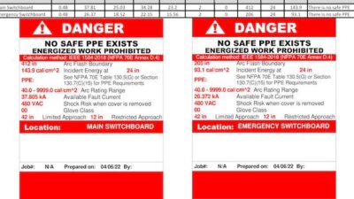
Labelling: One of the most important aspects of electrical system maintenance is proper labelling. To maximize safety, all components of electrical systems should be labelled with its name, voltage, source and any shock or arc flash hazards associated with the equipment. Equipment labelling plays an important role in every aspect of maintenance. Proper labelling:
- Helps keep track of what equipment has been maintained.
- Ensures that equipment power source is identified so it can be locked-out/tagged-out correctly before work is performed.
- Identifies the shock and arc flash hazards so electricians know what PPE is needed to safely perform work on energized equipment.
- Allows for faster restoration of service and troubleshooting after a fault event.
- Simplifies the collection of data for future designs, upgrades and arc flash/power system studies.
Arc flash analysis: NFPA 70E requires that arc flash analyses are reviewed every five years or whenever changes in the electrical system may influence the arc flash incident energies. Making sure the arc flash analysis and associated labels are up-to-date is critical to the safety of electricians working on or with the electrical system. This is because their PPE may be selected based on the arc flash label on a given piece of equipment. If the electrical system has been changed since the arc flash label was created, the incident energy at a given location may be higher and the PPE selected based on the outdated arc flash label may not be sufficient to protect workers.
Safety plan: OSHA and NFPA 70E require employers to document and implement an electrical safety plan. While this is the employer’s responsibility, the design engineer can support the owner in the development of the safety plan and help them make appropriate decisions.