Engineers must make informed decisions regarding the proper transformer sizing selection, electrical and mechanical requirements and impacts to the electrical system under different operating and loading conditions
Learning Objectives
- Learn major transformer characteristics, application and parameters.
- Understand the major criteria and approaches to determining proper transformer size.
- Learn how to use electrical power system software to perform simulations.
A transformer is a major component of an electrical distribution system with the most impact on system performance during steady-state (normal) operation and during system disturbances, such as a fault. Therefore, engineers must ensure that the transformer is appropriately sized for the specific application and can supply adequate power to the loads under designed conditions and standard guidelines.
Typical applications for such major equipment are industrial plants, commercial buildings, hospitals, office buildings, shopping centers, schools, apartment buildings, etc. The article is focused on dry-type transformer such as ventilated self-cooled, forced air-cooled, nonventilated self-cooled and sealed self-cooled power transformers less than 30 megavolt amperes and 34.5 kilovolts.
In general, dry-type transformers are less flammable (i.e., containing no liquids or oil) and carry less of a fire hazard, making them better suited for use in and near buildings. This type of transformer has a higher operating temperature and typically requires a larger footprint. Because dry-type transformers require air for cooling, it is necessary to provide an adequately sized ventilation system for the heat generated by the transformer.
The overall approach for sizing transformers and related system impact are similar for all types of transformer with different cooling classes.
Transformer site location
Careful consideration must be taken when selecting the proper location for a transformer. Several details, including transformer type, size, ventilation, atmospheric pressure, altitude, voltage level and clearance will have a determining factor in selecting the ideal location for the transformer required for a given installation.
An engineer must be aware of the limitations due to the selected location of a transformer. In general, the kilovolt-ampere ratings are based on temperature not to exceed 40°C ambient temperature (or ambient temperature of 30°C averaged over a 24-hour period, otherwise some decrease in life expectancy will occur) and also installed below 3,300 feet at sea level.
If any of these conditions are not met, transformer should be de-rated. In such case, transformer kilovolt-ampere should be de-rated by 8% for each 10°C above 40°C (when air-cooled for dry-type transformer) and also by 0.3% for every 330 feet over 3,300 feet altitude). More details for site consideration are discussed in NFPA 70: National Electrical Code Articles 450.8, 450.21 and 450.22.
Voltage class
The voltage class typically is selected based on available source voltage (e.g., utility source) and the required load voltage, if the load is designed to operate on a single- or three-phase system. The standard rated high-voltage transformers are: 2,400, 4,160, 4,800, 6,900, 7,200, 12,000, 13,200, 13,800, 23,000 and 34,500 volts. The low-voltage side includes 208, 480, 2,400 and 4,160.
Transformer winding connection and impedance
Standard connection arrangements and terminal marking are included in the standards for particular types of transformers in accordance with IEEE Standard C57.12.70. The most typical winding (phase) connections for power transformers, including angular displacement between high- and low-voltage, is shown in Figure 1. Based on this standard, the angular displacement of three-phase transformers with delta-delta or wye-wye connections shall be 0 degrees and wye-delta or delta-wye connections shall be 30 degrees.
In general, the selection of winding connections is mainly based on the overall system design, required system parameter (e.g., equipment short-circuit current withstand capability) and especially the system neutral grounding scheme. In addition, wye-connection can configure as one of the grounding types such as open (ungrounded), solid (solidly grounded, no intentional impedance in the neutral grounding path), resistor (a resistor is used in the neutral grounding path), reactor (a reactor is used in the neutral grounding path) and few other less applicable options.
The grounding configuration and scheme depends on the overall neutral grounding system in the facility. A wye solidly grounded transformer (secondary) is a typical application in facilities for a low-voltage system (e.g., 4.16 kilovolt:0.480 kilovolt).
In addition, Z (impedence, based on transformer self-cooled kilovolt-ampere ratings) is typically shown on nameplate information that is attached to front or inside transformer enclosure. This value has a high impact on electrical distribution system parameters such as voltage drop, available short circuit and incident energy. For example, choosing a higher impendence transformer (i.e., from 5.5% to 7.5%) can lower the available fault current allowing for equipment with lower amperes interrupting ratings, as long as there are no issues with system voltage within a facility.
ANSI C57.12.10 specifies typical impedance values for transformers larger than 500 kilovolt-amperes. This value depends on kilovolt-ampere rating and also high- and low-side transformer voltage ratings. For instance, %Z for transformer with high-voltage side less than 34.5 kilovolts is between 5.5% and 7.5%. Note that the typical %Z for 13.8 kilovolts (or less) on the high side and 2.4 kilovolts (or less) on the low side is 5.75%.
Most industry power transformers are included in this voltage level range. For a transformer less or equal to 500 kilovolt-amperes, a typical %Z impedance may vary between 2.3% and 5.2% based on the voltage level. For instance, a 100 kilovolt-ampere transformer with 8.32 kilovolts (or less) on the high side has a typical value of 2.6% impedance.
Transformer sizing for new systems
Due to the critical role of transformers in electrical distribution systems, it is essential that the transformer is sized correctly so that it can meet all applicable loading conditions. If it is undersized, it may create issues within electrical distribution systems, including loss of loads. In general, transformer sizing can be performed based on two methods:
- Connected load.
- Operating load.
In both cases, load growth and future facility modification and de-rating factors such as ambient temperature and altitude should be considered. The growth factor is typically based on each system design and can vary; 110% to 130% is a reasonable range. In both methods, the sizing is performed from the downstream system to the main transformer (i.e., bottom up).
The difference between these two methods is to determine a total connected kilovolt-ampere loads. There are several considerations that will determine which method to use, such as required design margin, project specification, cost, space availability and impact on voltage drop and available fault current.
The electrical distribution system of a typical industrial facility, such as a water treatment plants, is shown in Figure 2. The task is to evaluate the size of the new ventilated self-cooled transformer (or evaluate the size for the existing), based on its required loads, using the two methods previously mentioned.
Sizing Based on All Connected Loads
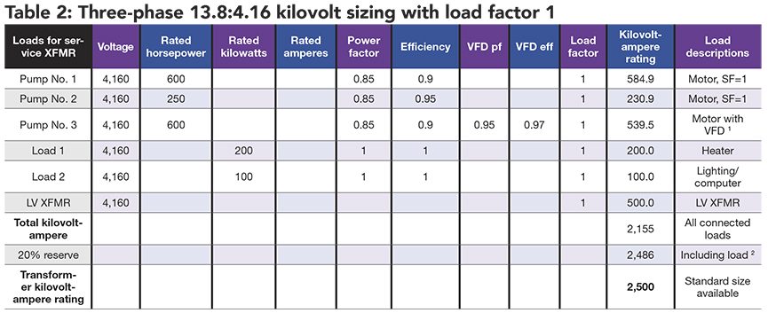
For sizing based on all connected loads, the conservative method, all connected loads are considered regardless of their operating condition and system function. The sizing is performed from the downstream transformer toward the main. As shown in Figure 3, the downstream transformer (LV XFMR) is three-phase at 4.16 to 0.480 kilovolts, and the main transformer (service XFMR) is three-phase 13.8 to 4.16 kilovolts supply to different type loads (e.g., motor loads, variable frequency drives, static loads, distribution panel).
The individual loads with their corresponding system parameters such as rated horsepower, power factor, efficiency and load factor are tabulated in Tables 1 and 2. Total kilovolt-ampere of the connected system is calculated including design margin and then the next available standard size will be selected.
The typical standard size kilovolt-ampere for three-phase transformer based on ANSI C57.12.00 typically range between 15 and 100,000 kva which are based on the output of the transformer. The input kilovolt-ampere is expected to be higher by 1% to 5% (i.e., refers to transformer efficiency) due to transformer losses in its core and windings, dissipated as heat. These flows for each transformer are shown in Figures 3 and 4.
In general, unless specified, transformers should not be overloaded and should be approved by the manufacturer for any short-time overloading operation due to the lower ambient temperature.
The evaluation of data and kilovolt-ampere transformer selected size tableted in these tables are confirmed and analyzed by performing load flow analysis using ETAP electrical software. Power (kilovolt-ampere) flow for each branch including percent voltage (of nominal rating) and fault current for the major switchgear and motor control center is shown in Figure 3.
Sizing Based on Actual System Operations
For sizing based on actual system operations, all connected loads will be considered based on their operating conditions (i.e., load factors). As with connected loads, the sizing is performed from the downstream transformer toward the main with the same process. Total kilovolt-ampere including design margin, load factors and the selected transformer size are calculated and shown in Tables 3 and 4.
The evaluation of the same system with different transformer sizes is shown in Figure 4. Power flow for each branch including percent voltage and fault current are also shown for the major switchgear and MCC.
In addition, there are a few results that should be noted when comparing Figures 3 and 4. First, the connected loads method is a more conservative approach when sizing the transformer and will provide better system voltage profile on the secondary side, but it generates and injects more fault current. This is mainly due to higher kilovolt-ampere transformer rating and consequently higher short-circuit injection to the system.
Table 4: The individual loads with their corresponding system parameters such as rated horsepower, power factor, efficiency with different load factors are tabulated to determine the medium-voltage transformer size. Courtesy: CDM Smith[/caption]
It is also important to point out that a K-factor rated transformer is recommended to size the transformer due to heat generation if the facility contains high harmonic generating sources, typically more than 15% total harmonic distortion. The K-factor will determine how much a transformer should be de-rated or oversized to handle such a system. Refer to ANSI/IEEE C57.110 for more details.
Transformers play a critical role in ensuring proper power system operation. They should be carefully sized and selected when designing and analyzing electrical distribution system to provide reliable and safe power system operation. The proper transformer sizing should consider applicable de-rating factors such as ambient temperature and altitude and, in addition, impacts on electrical distribution system voltage and fault current contribution.