Learn how to define the procedures of electrical schematic design, design development, construction documents, bidding, and construction administration including electrical commissioning.
Learning Objectives
- Understand the expectation of drawing information at each step of electrical design.
- Learn about the procedures of how to obtain this design information.
- Know how to implement the information obtained to complete a building project.
The primary goal of any building electrical design is to provide a safe, energy-efficient system that meets the client’s needs and is in compliance with codes. Life safety and preservation of property are two of the most important factors in the design of the electrical system.
NFPA 70: National Electrical Code (NEC), the International Building Code (IBC), the International Energy Conservation Code (IECC), the International Mechanical Code (IMC), the International Plumbing Code (IPC), the International Fire Code (IFC),the International Swimming Pool and Spa Code (ISPSC), the Building Industry Consulting Service International (BICSI), and other various codes provide rules and regulations to meet the minimum requirements to protect life and property. The electrical designer must meet these requirements for it to be a successful, code-compliant design.
Electrical system requirements for large facilities
The following are systems and equipment that typically are provided to satisfy functional requirements within large facilities:
- Building electrical service(s).
- Robust power distribution systems (NEC Article 700: Emergency, NEC Article 701: Legally Required Standby, NEC Article 702: Optional Standby).
- Lighting: interior and exterior (general, decorative, and task).
- Communication systems: telephone, data, TV.
- Fire alarm systems.
- Smoke-control systems.
- Transportation: elevators, escalators, moving walkways.
- Space conditioning and control: HVAC, building automation systems (BAS).
- Plumbing: hot- and cold-water systems.
- Security: electronic access systems, closed-circuit surveillance TV.
- Refrigeration equipment for kitchens.
- Food handling, dining facilities, and food preparation facilities.
- Lightning protection.
- Specialized audio/video systems for entertainment.
The following typically is provided by an architect seeking a fee to provide electrical engineering for permit and construction. Our example will include the following parameters:
- A high-rise hotel of 40 stories and 3,000 guestrooms.
- Guest rooms will consist of three types: a single-bay 450-sq-ft unit, a two-bay 900-sq-ft unit, and a three-bay 1,350-sq-ft suite.
- Three interior stairwells.
- An elevator bank of eight elevators, four accessing the first 30 floors and four high-speed accessing the upper 10 floors.
- A low-rise component containing a 100,000-sq-ft casino with 2,500 slot machines and 30 table games, such as blackjack, craps, etc.
- A convention facility of approximately 75,000 sq ft.
- A prefunction area of approximately 20,000 sq ft.
- A main kitchen of approximately 7,500 sq ft.
- A buffet of approximately 15,000 sq ft.
- A food court for six food vendors, each occupying approximately 4,000 sq ft.
- An open parking garage of approximately 6 stories and 1,500 spaces.
- Two 20,000-sq-ft restaurants with 6,000-sq-ft kitchens each.
- A small showroom of approximately 35,000 sq ft and 800 seats for an evening show of musical variety.
- A center sports bar with about 40 seats, approximately 2,500 sq ft.
- A sports book of 2,500 sq ft.
- Back-of-house offices, repair shops, electrical/mechanical rooms, central plant, corridors, employee bathrooms, etc. of approximately 400,000 sq ft. These are spaces the public typically never sees.
- A porte-cochere of 3,000 sq ft.
- A retail concourse of approximately 60,000 sq ft including the concourse. This has approximately 15 shops.
Schematic design phase for electrical systems
The schematic design (SD) phase sets up the general concept for the electrical design, and the expectations of it may vary widely from project to project based on factors such as construction estimates, deadlines, construction phases, project size, etc. As a first step, preliminary architectural drawings should be provided to the engineer to begin the design process and understand the complexity of the project. A list of questions should be generated based on the preliminary information to further define the scope.
The list of questions should be clarified during a kickoff meeting with the owner, architect, civil engineer, mechanical, electrical, plumbing, fire protection (MEP/FP) engineers, and other design professionals. In addition, during this meeting, the team should review preliminary floor plans, owner design standards/requirements, the project schedule, and expectations for each of the deliverables, phases, and packages in which the project will be separated.
A typical large facility may include a tower package, a podium package, and a parking garage package. These separate packages allow for associated construction to begin before later packages are completed. After attending the kickoff meeting, the electrical engineer should have a better understanding of the project scope and owner’s design standards. This should allow the engineer to develop the preliminary scope of work and develop the basis of design (BOD) for the project.
The first step for the electrical team is to set up the electrical drawings for the SD package based on the preliminary architectural drawings received. Electrical drawings should include an overall site plan and overall floor plans for the tower, podium, and parking garage packages, which will be used for the coordination of all the major electrical rooms and equipment distribution.
Next, the team will spend some time reviewing the owner’s design standards to understand the power requirements for different areas of the building, and then research applicable codes including the NEC and energy and local codes to determine the systems’ needs based on building areas’ occupancy types.
Planning for the design of an electrical system for facilities of this size should begin with the determination and study of the size and nature of the total load to be served. This means load estimates on watts-per-square-foot basis and the estimation of the amount of other utilization loads and their concentrations throughout the building. Understanding of the major loads/equipment power requirements and their location in the building is essential to the selection of the recommended distribution systems.
Once the list of SD coordination questions has been responded to and most of the building occupancy types have been identified on the plans, the task for the electrical engineer is to prepare a rough estimate of electrical loads based on NEC Article 220. Consider the estimated connected loads with demand factors, diversity factors, and historical data. Our experience on large hotels is a 25% loading of transformers sized per the NEC and 35% loading of podium transformers. Service entrance equipment is typically estimated at a load of 35% to 45%. The preliminary generator load also should be estimated.
Once preliminary loads have been completed and utility service and switchgear ampacities have been estimated, a preliminary electrical system should be developed. The single-line diagram should include the main switchgear, step-down transformers from medium-voltage system to 480/277 V distribution, generators, automatic transfer switches (ATS), uninterruptable power supply (UPS), optional standby systems, 480V/277 V distribution boards, 480/277 V to 208/120 V transformers, panelboards, feeders, preliminary connections to chillers, air handling units, fire pumps, hydronic heat pumps, cooling towers, elevators, etc.
The electrical system should include a topology, such as branches of power (mechanical, life safety, general purpose, lighting, etc.), and careful planning for future increases in electrical use. Conductors are not typically sized at this time for feeders because it is very preliminary. Submit the preliminary site plan with the preferred service point(s), preliminary single-line diagram, and estimated loads to the dry utility coordinator or directly to the serving utility for the preliminary work of serving the property. It is recommended to request available fault-current values form the serving utility at this time.
The electrical engineer should provide the architect with preliminary electrical room layouts to coordinate appropriate locations of major electrical equipment throughout the building. The electrical engineer is responsible for coordinating the space requirements for a proper electrical installation per NEC Article 110.26 requirements. In addition, the requested room spaces to house electrical equipment also should be able to accommodate the addition of future equipment. Equipment weights and sizes are estimated at this phase to assist the architect, structural engineer, and mechanical engineer with egress, structural coordination, and cooling needs.
Electrical system design development phase
The design development (DD) phase focuses and refines the electrical design. The architect should provide a further developed architectural set of drawings for the different areas of the facility. By now, the architectural drawings should include enlarged plans, preliminary reflected ceiling plans for back-of-house areas, kitchen areas, offices, restrooms, employee break rooms, etc. The architect should send its DD set to all the design professionals to continue developing their design.
It is during this early period that the electrical designer should emphasize the need for duct bank routing, structural reinforcement for heavy equipment, electrical rooms’ wall ratings (if required), clearances around electrical equipment, egress doors for electrical rooms, transformers, busways, cable trays, panel boards and switchboards, and other items that may be required. It is much more difficult to obtain such things once the design proceeds to construction documentation (CD).
The electrical team should provide DD coordination questions to the architect and other consultants based on the owner’s expectation for the electrical design at this phase and the progress of other design professionals’ needs of electrical coordination, such as a kitchen consultant.
The goal for the electrical team in this phase of the project is to coordinate and lay out most of the back-of-house equipment, lighting, receptacles, and mechanical, plumbing, and power requirements from equipment specified by other consultants. Little, if any, branch circuitry is provided at this phase.
Depending on the order in which the information is received from other consultants provide, the team should plan on which areas to focus first. The electrical drawings included is typically as follow:
- Electrical cover sheet.
- Lighting fixture schedule(s).
- Site plan(s).
- Overall plan(s).
- Power plan(s).
- Lighting plan(s).
- Enlarged electrical room plan(s).
- Enlarged food service plan(s).
- Enlarged specialty lighting plan(s).
- Enlarged guest room unit plan(s).
- Single-line diagrams.
- Panels and dimmer schedules.
Electrical cover sheet—This drawing typically includes the electrical drawings sheet index, abbreviations, and electrical symbol legend.
Lighting fixture schedule—Incorporate preliminary front-of-house lighting specifications from the lighting consultant, if available. A back-of-house luminaire schedule will be created because these areas typically are under the responsibility of the electrical engineer.
Site plan—The electrical site plan should include the lighting layout only, based on the lighting consultant’s design supplemented with back-of-house lighting of areas not accessible to the public. For instance, parking lot pole lights, walkways, and landscape lighting typically are provided by the lighting consultant. Building-mounted signage, site signage, and any of the site water features’ power requirements also should be identified.
A dry utility consultant should assist the civil engineer, the local electric utility, and owner’s representative with the site utility requirements. Utility switchgear and/or utility-furnished transformer locations should be indicated on the electrical site plan. Understanding the proposed routing, design, construction, etc. on site for the electrical utility, is important to understand at this phase.
Overall plans—Overall plans should include the electrical distribution equipment layout at each building level including main switchgear, generators, distribution boards, UPS equipment, panel boards, ATS, etc. Identify walls to the architect that should be 6 in. thick for recessed flush panels.
Power plans—Provide receptacle outlet layouts for back-of-house areas. Consider providing convenience receptacle outlets along the guest room tower corridors at possibly 50 feet on center, determine the estimated quantity of 20-amp branch circuits needed in the typical guest room, typically three for a standard guest room. For front-of-house areas, place convenience receptacles as required per code and additional ones as indicated by the interior designer, architect, and owner. Review all architectural, interior design, elevations, typical rooms, and other consultant drawings for outlet locations required, and capture them in this drawing set.
Coordinate spa, pool, internally illuminated signage, security/surveillance, telephone/data, and audio/video equipment power requirements with the design consultants in order to develop and design the supporting electrical infrastructure.
Incorporate mechanical and plumbing equipment layouts per the design consultants’ requirements. Provide rooftop weatherproof and weather-resistant receptacles within 25 ft of mechanical equipment. Coordinate the elevator machine room, pit, shaft, and possibly top-of-elevator lights, switches, and receptacle requirements.
Advise the architect and owner which equipment loads are required to be on emergency (NEC 700) or legally required standby (NEC 701) power per code. Confirm with the architect and owner which equipment loads will be preferred to be connected to optional standby (NEC 702) or UPS power to properly meet the owner’s needs. Provide the preliminary emergency/legally required/optional standby power systems design and include generator sizing and selection, the transfer system, preliminary load prioritization, load-shed criteria, and segregated emergency/legally required and optional standby distribution systems.
Generator fuel, storage, and quantities also should be reviewed at this time. Any and all outlets indicated in architectural drawings need to be captured on electrical power plans. A thorough review of all architectural floor plans, elevations, and typical rooms is required.
Lighting plans—Preliminary lighting-load allowance per area calculations for the back of house and front of house should be performed based on the applicable energy codes. The electrical engineer should notify the architect and lighting consultant of the lighting allowances, so they can design their lighting layouts to meet the energy requirements for each area and to understand control requirements for the applicable codes. There is a high level of coordination needed for architectural, interior design, mechanical design, and lighting plans in electrical drawings.
Preliminary back-of-house and front-of-house lighting layouts for normal and emergency lighting should be included. Back-of-house lighting cutsheets should be provided to the architect for review and approval. The electrical design team should provide rough photometric calculations to indicate preliminary compliance with emergency lighting footcandle requirements along the path of egress (1 fc is average). Emergency lighting should be considered in areas such as electrical rooms, stairways, information technology rooms, etc. Exit signage should be placed on the drawings and coordinated with the other design professionals’ egress plans. Exterior emergency lighting above discharge doors should also be included on the drawings. Finally, lighting controls for back-of-house areas should be added to the plans based on applicable codes (NEC and energy).
Enlarged electrical room plans—Create enlarged 0.25- to 1-in.-scale plans for all electrical rooms. Show equipment clearances and electrical room egress door requirements per NEC Article 110.26.
Enlarged food service plans—Create enlarged 0.25- to 1-in.-scale plans for food service areas, which are sometimes handled by a separate consultant. Food-and-beverage electrical systems are based on the food service consultant’s bulk loads and equipment locations. Place ground-fault circuit interrupter (GFCI) receptacle outlets per NEC 210.8(B)(2) within kitchen areas for food service power connection.
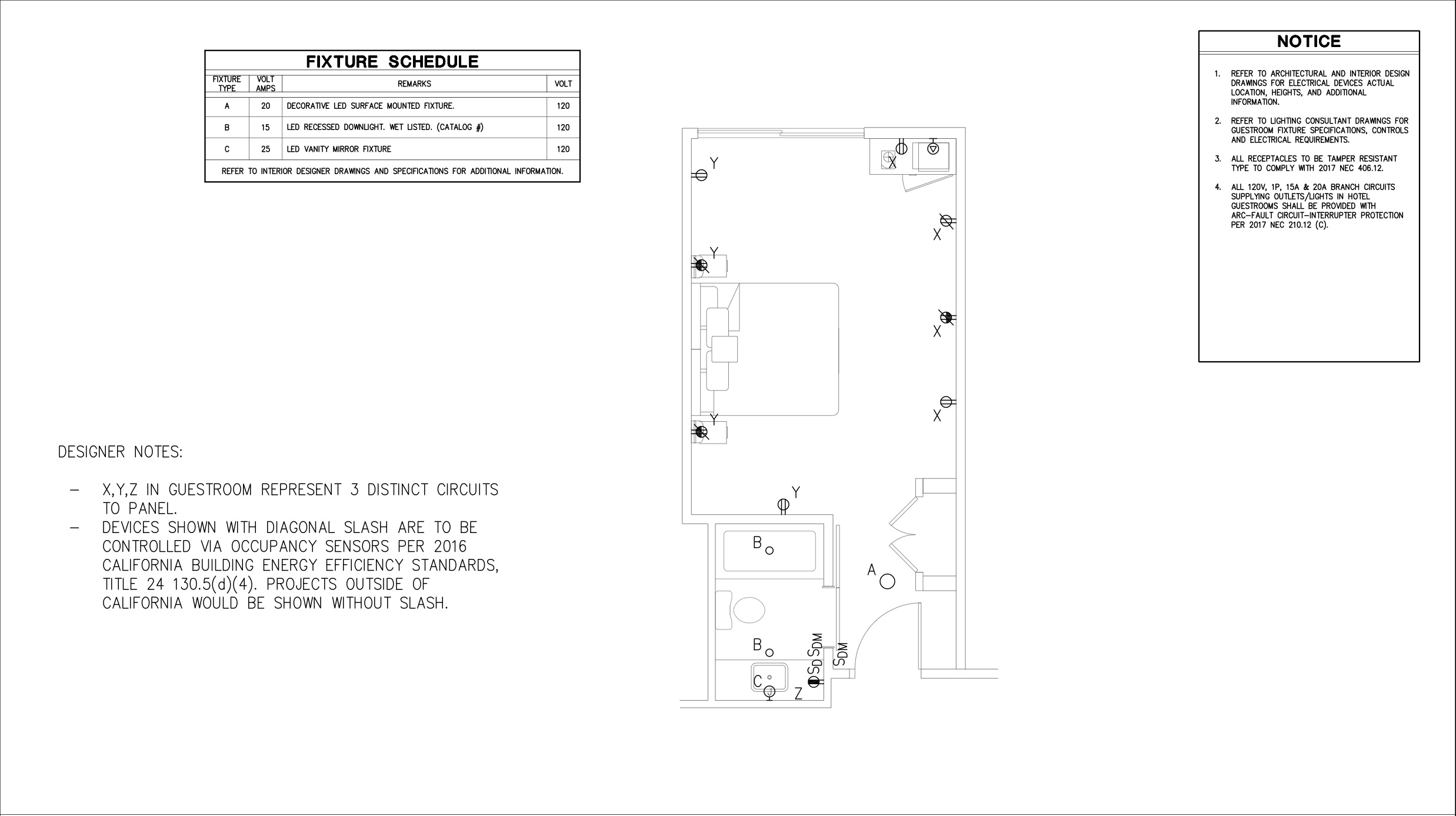
Enlarged guest room unit plans—Develop the design for the typical enlarged (typically 0.25- to 1-in.-scale) guest room units based on information provided by the architect/interior designer. Receptacle layouts shall comply with NEC 210.8(A), 210.12(C), and 210.60 requirements.
Single–line diagrams—At this point, the single-line diagram is expanding as electrical distribution systems are being added because different areas in the building are being further developed. Feeders or empty conduits stubbed into all tenant spaces should be incorporated. Update the single-line diagrams to include equipment ratings for main switchgear, generators, ATS, distribution boards, transformers, motor control centers, panel boards, etc.
The single-line diagrams should then be prepared in conformity with the serving utility’s requirements. Send updated single-lines, estimated load calculations, and the site plan, including the recommended service location, to the serving utility for their review. Determine owner- and utility-furnished items. If fault-current values have been received from the serving utility, short-circuit calculations can begin in this phase of design.
Panels and dimmer schedules—Create the preliminary panel and dimmer schedules.
Book specifications—Typically for these types of projects, MasterFormat Division 26 specifications will be provided. Sections should be included based on project requirements.
Along with the DD package submitted to the architect, the electrical team should send an updated coordination list requesting information required from the owner, architect, and other consultants to proceed to the next phase of the design. This is the time to review the electrical drawings with the owner and owner’s staff to coordinate specific needs. By reviewing with key personnel, changes in the construction document (CD) phase are avoided and the owner is a clear part of the design process.
Electrical design construction documentation for commissioning
The CD phase fills in the details of the electrical design. The architect should provide finalized architectural drawings for all the different areas of the project along with any comments from the submitted electrical DD package for the commissioning phase. Architectural drawings should include all floor plans, enlarged plans, reflected ceiling plans, details, elevations, etc. for all areas of the building. The architect should distribute its construction documents to all the design professionals involved in the project to complete their design.
The design from the food service, interiors, low-voltage, lighting, vertical transportation, fire sprinkler, landscape, mechanical, plumbing, pool, structural, or other specialties should be finalized during this phase of the project. The electrical team typically is at the end of the line waiting on all other consultants’ information to finalize the electrical design. For this reason, it is important to request final information in a reasonable amount of time before the permit drawing set is scheduled to be issued.
To ensure everything has been provided as requested, it is during this phase that the designer should review the requested electrical spaces and clearances for electrical rooms, panel boards, motor control centers, and switchboards.
Plan-checking by the local building authority is an essential part of the permitting process. Finally, upon satisfaction of the plan reviewers, the CD set is ready to be issued to construct.
Electrical cover sheet—The electrical design team should verify the electrical symbols used in the electrical drawing set are incorporated into the electrical symbol legend. The sheet index should include all the electrical drawings.
Lighting fixture schedule—The back-of-house and front-of-house, site, façade, and guest rooms lighting-fixture schedules should include wattage, voltage, and driver type.
Energy–compliance forms—Include energy-compliance form calculations to demonstrate compliance with the applicable energy codes.
Site plan—The site lighting should be circuited, and lighting controls defined. Building-mounted signage, site signage, and any site water features’ power connections and controls should be finalized.
Coordinate the location for generator(s), utility switchgear, and/or utility-furnished transformers and indicate them on the site plan. Electric vehicle charging stations should be shown if required by the codes or owner needs.
Overall plans—Verify that the electrical distribution equipment being used at each level of the building is included and clearly identified.
Power plans—Include circuiting for all devices and equipment indicated on the other design professional drawings. Clearly define the power system it is connected to (i.e., emergency, legally required standby, optional standby, UPS, etc.).
Lighting plans—Complete the back-of-house and front-of-house lighting circuiting, controls, and exit signs.
Enlarged electrical room plans—Finalize enlarged 0.25- to 1-in.-scale plans for all electrical rooms.
Enlarged food service plans—Complete the enlarged plans for food service areas by indicating all circuiting. Kitchen demand loads should be applied per NEC 220.56 and Table 220.56.
Enlarged guestroom unit plans—Finalize the circuiting and lighting/controls design for the typical enlarged guest room units based on information provided by architect/interior designer and other consultants. Consider the demands allowed by NEC Table 220.
Single-line diagrams—Finalize the single-line diagrams based on final design modifications and updated load analysis. Include feeder schedules, notes, load calculations (based on the design’s connected load), the equipment schedule indicating equipment specs, etc. Provide selective coordination per NEC Articles 700.32 and 701.27. Provide fault-current analysis and voltage-drop analysis.
Panels and dimmer schedules—Finalize panel boards and dimmer schedules to include the ampere-interrupting-capacity rating, main lug only/main overcurrent protection, branch circuit breaker ratings, load volt-amps (VA), and load description.
Book specifications—Update MasterFormat Division 26 book specifications based on final design modifications. Review other sections of specifications, such as fire alarm, low-voltage, mechanical, and plumbing, to make sure coordination is achieved and the direction is clear and concise in compliance with code.
Bidding and construction administration
Once a completed set of construction documents has been issued and approved by the owner, it is ready for bid. The owner should submit the drawings to interested contractors, who will then bid the cost to construct the job.
Perform site observations during the construction phase to survey the status of the systems’ installations. Review the contractor material submittals and shop drawings. Respond to requests for information and field-coordination issues.
Commissioning for electrical systems
Electrical commissioning (Cx) is an important step of the construction and design teams, and for the owner to understand, including what equipment will be reviewed and how it will be reviewed. This can be broken into several steps:
- Visual observation of all electrical equipment including components within electrical equipment, such as busing and cables, to confirm the equipment provided agrees with the drawings and specifications as produced by the engineer of record for commissioning. This includes making sure that proper listing and labeling is completed and that the equipment provided is in compliance with its listing. Also, confirmation that the equipment being furnished and installed is in compliance with the specifications and manufacturers requirements.
- Functional testing, such as ground-resistance measurements, relay settings on protection devices, ground-fault protection testing, and GFCI/arc-fault circuit-interrupter testing, is an observation of the contractor operating the equipment in question to confirm its operation is as intended by the design documents and in conformance with codes. Also, load bank testing of generators to verify full functionality, paralleling equipment testing for a variety of agreed-upon scenarios, and fire pump starting as well as fire-smoke control interfacing to electrical systems for commissioning.
- Preventive maintenance base-point measurements for infrared scans of all equipment terminations, and ampacity and voltage readings for all equipment. Depending on the Cx scope, Cx organizations represented by the commission agent (CxA), and possibly U.S. Green Building Council LEED certification, certain requirements are outlined for documentation due to the owner. Also, review of operations and maintenance materials, a process for resolving issues pointed out by the CxA, etc.