A Nebraska school district embraced outside-the-box HVAC design to connect existing facilities and new construction into an efficient engineering solution.
Learning objectives
- Consider outside-the-box solutions when replacing a boiler system.
- Explore 3-D visualization, which improves integrated design when locating new equipment in an existing space.
- Recognize that a boiler layout that complies with manufacturer’s recommendations may not comply with local boiler codes.
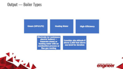
In the nonresidential building world, mechanical engineering systems are evolving to more efficient and innovative solutions. Multiple HVAC options exist when considering the type of central boiler plant. The final design choice depends on the requirements of the specific installation. For applications involving only space heating and domestic water heating, a low-temperature water system is generally sufficient. A low-temperature water system is defined as a water-heating system up to 250°F and operating at less than 160-psig pressure.
With the availability of these new and more efficient systems comes the responsibility of understanding not only how they operate, but also how they align or fail to align with codes and design standards established by school districts, cities, counties, and state-mandated codes.
The Beveridge Magnet Middle School project with the Omaha Public School District (OPSD) exemplifies not only how this issue was resolved, but also considers how engineers can up their design game using outside-the-box solutions and 3-D visualization.
The Challenges
OPSD commissioned DLR Group to upgrade and expand the Beveridge Magnet Middle School. The school, constructed in 1964, had minimal updates and improvements to its learning environment over its more than 50 years of service. The challenges in this project included adding a 6th grade to an existing school that housed 7th and 8th grades only.
The scope of work for this project included renovation of the existing 128,000-sq-ft building, a building-envelope facelift, and 28,000 sq ft of building additions to accommodate additional classroom spaces for the 6th grade and some new programs for the school. The renovation also included the removal of seven modular classroom structures and a complete redesign of the school’s entrance. The update included an entirely new HVAC system.
Phasing the construction work kept the school operational during construction. Because of this phased construction, the steam boiler plant and steam distribution piping had to remain operational to provide heating to those areas of the building that were to remain occupied. The mechanical scope of work was to replace the existing HVAC system with a new centralized heating and air conditioning system that would serve the school. This project integrated the school’s new HVAC system into the districtwide building automation and control system.
The new-construction square footage provided mechanical equipment space to serve the new building additions. However, additional square footage was not available for the HVAC upgrades designated for the existing school. This posed a phasing challenge, as the team was tasked with replacing the existing mechanical equipment by renovating and/or repurposing existing space all while keeping the building operational so the school could remain in session throughout the winter.
Phased integration
The school, originally designed for heating only, was served by three low-pressure steam boilers. Two boilers were 9,100-MBh capacity each and the third boiler was 4,600-MBh capacity. It is common in northern states, such as Nebraska, to size heating (boiler) systems with redundancy. For example, a boiler plant designed with each boiler sized at 65% to 75% of the building’s peak design load allows for redundancy in the event of a single boiler’s failure.
In the case of this building, the smaller third boiler was a “base load” boiler used primarily for domestic water heating via a steam-to-water heating-tube bundle and a domestic water-storage tank. This type of boiler plant design was common for this era of time where a base load boiler was designed to handle the heating load when the heating demand dropped below the low-firing rate of the main boiler(s). The base load boiler also was used to provide domestic hot water when little or no heating load exists, such as in the summer.
The system was energy-inefficient when compared with today’s boilers, as the existing burners only had a 3:1 turndown ratio to attempt to meet variations in heating demand. With this limited turndown ratio, the existing boilers would need to cycle on-off repeatedly at low loads.
Because no additional building mechanical space was available, it was understood the existing HVAC system needed to be replaced while keeping the existing system operational throughout the winter heating season. Best practice is to attempt to have two boilers operational to provide redundancy in the event of a single boiler’s failure. As the design team was exploring options for the HVAC system replacement, the district informed the team that the base load boiler was not functional, so the area occupied by that boiler within the mechanical room was available for installation of some new equipment.
Boiler options
The first option was to contact a local company, Rasmussen Mechanical Services, about renting a mobile steam boiler plant system. Rental costs and the logistics for integrating the mobile boiler plant into the school’s existing steam system were evaluated. In general, the concept was to extend steam and condensate piping to the exterior of the building to allow interconnection of the mobile steam boiler plant system and the school’s existing steam system.
The plan located the mobile steam boiler plant system/trailer in the school’s parking lot during the winter heating season to serve as the school’s standby boiler system. In having the mobile steam boiler plant as the backup boiler system, the area occupied by one of the large boilers also would be available for installation of new equipment within the mechanical room. While this was a clever solution, it didn’t fit into the project construction budget.
With the mobile boiler plant option off the table, the next step was to try to find additional mechanical-room space within the building. Programmatically, this proved impossible without compromising other educational-space needs. With the project at its budget limit, the engineering team discussed with OPSD the challenges of not having any new designated mechanical space to allow replacing the existing mechanical system/equipment while simultaneously keeping the existing mechanical system operational. Convinced that OPSD understood the options and the risk factors, the decision was collectively made to go through the winter construction season with one boiler.
This collaborative decision allowed the design team to remove the nonoperating base load boiler as well as the backup boiler, which began to provide the space necessary to construct the new HVAC system for the school—a boiler-tower water-source heat pump system, sometimes referred to as a California Loop heat pump system. With a boiler-tower heat pump system, the heat pumps are all piped to a common piping loop and the water-loop temperature is maintained between 60° and 85°F by a cooling tower and a boiler system.
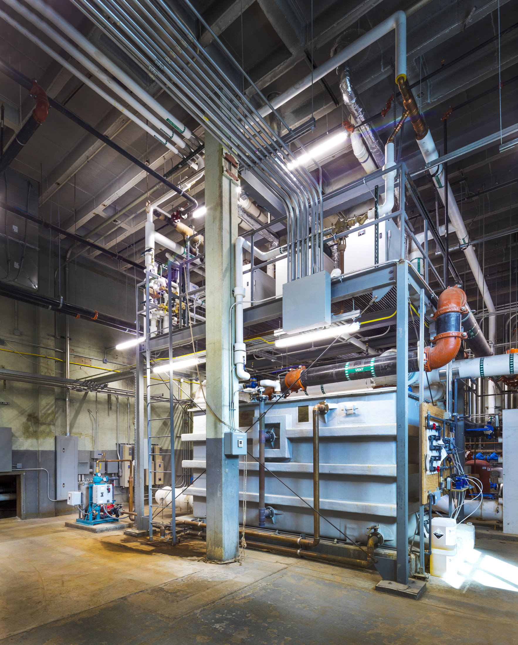
The new boilers, boiler pumps, cooling tower sump tank, plate-and-frame heat exchanger, water-loop pumps, and accessories were all planned to be located in the existing boiler room. Heat rejection was provided by a cooling tower located outdoors adjacent to the boiler room. Heat addition to the heat pump water loop was provided by two 2,175-MBh-output high-efficiency, condensing, hot-water boilers. These new boilers were placed in the existing boiler room in the space made available after the removal of the old boilers.
Modulating, condensing boilers were used for heat addition to the heat pump water loop. Condensing boilers operate most efficiently when they are operating in condensing mode, which generally occurs when a boiler’s return-fluid temperature is at or below 130°F. In the case of the Beveridge Middle School, the boiler system added heat to the heat pump water loop, which was designed to be maintained between 60° and 70°F during the heating season. With a 60°F entering-water temperature, the condensing boilers operate at an efficiency of more than 95%.
Ultimately, the water-source heat pump system proved the best option for the Beveridge Middle School project because it provided a balance of low first-cost along with good energy performance and addressed these as project goals.
Integrated design solution
Even after removal of one heating boiler, as well as the base load boiler and the domestic water tank, the design team realized that additional mechanical space was needed to fit the required mechanical components into the recovered space. An integrated design process allowed the design team to come up with alternative options to the spatial constraints within the mechanical room. The mechanical, structural, and architectural disciplines were able to collaborate in a shared Autodesk Revit model visualizing what the final mechanical room layout could look like.
Through this process, a steel-framed mezzanine was added to provide additional floor space to accommodate the new domestic water-heating system. The existing boiler room height was 23 ft from floor to roof deck due to the physical size of the existing steam boilers. The mezzanine was located approximately 12 ft above the boiler room floor to provide the required clearances above the new boilers while providing ample space for the water-heating system.
Lessons learned
Codes and specifications: When using newer systems, engineers must be mindful of local codes and requirements that boiler inspectors expect to see. These include specific clearance requirements or methods of installation that go well beyond the manufacturer’s specified requirements. It’s important to work with the installing contractor to confirm these requirements are met; an experienced contractor will contribute to the integrated design process to communicate the highest standards to meet inspection codes.
For example, Nebraska requires 36-in. clearance around all boiler installations, which was a larger clearance than the manufacturer recommended. Ultimately, making these adjustments during design rather than needing to move boilers further apart after they are installed will save time and money for any project.
Piping details: Refer to the boiler manufacturer’s installation and operation manual as well as local codes for suggested piping diagrams. Understand the piping diagrams can vary, as each boiler manufacturer has its own heat-exchanger design/material and restrictions. It is important to consider this when providing a piping schematic/detail for the boiler’s installation.
Venting: Install the boiler vent and combustion-air vent/piping materials per the boiler manufacturer’s installation and operation manual. All manufacturers publish length limitations. In northern climates, consider the prevailing winds; they can cause freezing of condensate and water/ice buildup can occur at the vent termination, potentially blocking the vent pipe.
Water quality: Some boiler manufacturers are very strict about the system water quality. The proper water quality helps extend the life of the boiler by reducing the effects of limescale buildup and corrosion in closed-loop systems. Water quality outside of the boiler manufacturer’s optimal conditions also may void the boiler warranty. Consult with the boiler manufacturer to confirm the site’s water quality falls within their acceptable ranges for operation.
Neutralization kit: Use a neutralization kit when specifying condensing boilers. Carbonic acid forms inside condensing boilers when carbon dioxide mixes with water. A condensing appliance can produce 1 gal of condensate for every 100,000 Btus burned. The acidic condensate could damage the floor drain and drain pipes. Many municipalities do not allow piping of the acids directly to the drains without a neutralization kit. The neutralization kits raise the pH to levels acceptable for drainage in the plumbing system. The designer also should be aware of the depth of the neutralization kit and adjust the height of the boiler housekeeping pad to ensure the boiler’s condensate can drain by gravity to the neutralizing kit and ultimately to the floor drain.
Every project requires unique solutions, but when faced with a seemingly impossible engineering scenario, thinking outside the box of traditional designs not only results in creative problem-solving but also in thoughtful interaction with clients. This project presented numerous opportunities for communicating details using 3-D technology, which ultimately helped build trust between the entire design team throughout the integrated design process.