Water-cooled chillers are commonly used in the HVAC industry to provide cooling as part of a chilled water hydronic system. A full understanding of how these chillers operate and how they are affected by various design conditions can help a design engineer prevent operational issues in the field.
Learning objectives
- Understand how the refrigeration cycle operates in the context of water-cooled chillers.
- Learn about common operational issues that can happen at part-load and winter conditions.
- Identify several design solutions that can help mitigate operational issues.
Chiller insights
- A chiller is a key component in large commercial HVAC systems, using the refrigeration cycle to remove heat from chilled water that cools building spaces and transferring that heat to a condenser water loop that rejects it through cooling towers.
- Proper chiller operation requires careful control of lift and head pressure — especially during low-load or cold-weather conditions — to prevent issues such as unstable refrigerant flow, poor oil return, evaporator freezing or compressor damage.
In many large-scale commercial buildings greater than 150,000 square feet — such as laboratories, hospitals and higher‑education buildings — the primary method of cooling is accomplished through the use of chillers. A chiller is a piece of equipment that utilizes refrigerant and the refrigeration cycle to create cool, or “chilled,” water that is distributed to secondary heating, ventilation and air conditioning (HVAC) systems throughout the building.
In general, the chilled water is used in an HVAC system to cool the air in occupied spaces and “back of house” spaces, such as electrical rooms, mechanical rooms or telecommunication closets.
There are two major categories of chillers:
- Air-cooled, which rejects heat from the chiller refrigeration system to the outside air.
- Water-cooled, which rejects heat from the chiller refrigeration system to a warmer water loop, technically defined as a condenser water loop.
Though these chiller types are similar, this article will focus on the fundamentals specific to water-cooled chillers and common operational issues.
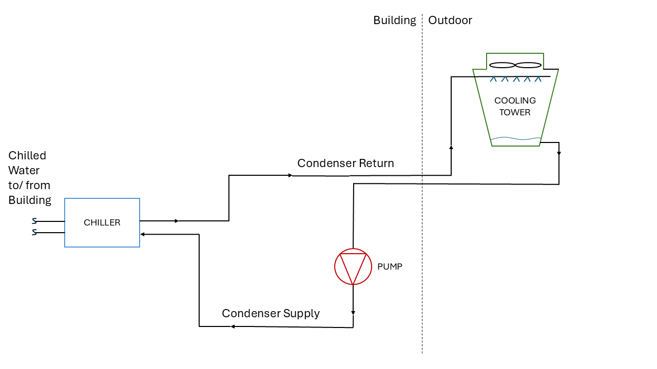
In a water‑cooled chiller, the refrigeration cycle, driven by the compressor, absorbs heat from the chilled‑water loop and transfers that heat into the warmer condenser‑water loop where it can be rejected by downstream equipment. In general, to reject the heat absorbed by the condenser‑water loop from the chiller, the most common approach is to pair it with one or more cooling towers, often counterflow induced‑draft towers, where the upward‑moving air stream passes opposite the downward‑falling water to maximize heat transfer.
The system works by pumping warm condenser water from the chiller to the top of the cooling tower, where spray nozzles disperse the water into a fine mist, while large fans draw or blow outside air through the tower (see Figure 1). This allows for large amounts of heat to transfer from the water to the air through evaporative cooling. As some water evaporates and releases heat into the air, the remaining liquid is cooled and collected in the bottom of the cooling tower in a basin to be pumped back to the chiller.
The temperature of the condenser water supply primarily depends on the outside wet bulb temperature. Wet bulb temperature refers to the lowest temperature that can be achieved through evaporation and is generally lower than the concurrent dry bulb temperature.
For example, if it is a 95°F day, but the wet bulb temperature is 75°F, the cooling tower could cool condenser water to 80°F to 82°Fbecause it is relying on evaporation, not conduction, to reject heat. As the wet bulb temperature decreases from a design day condition, the cooling tower leaving water temperature can also decrease if the airflow through the tower remains constant.
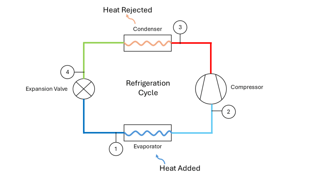
To transfer heat from the building chilled water loop to the condenser water, chillers rely on the thermodynamic process called the refrigeration cycle. The refrigeration cycle consists of four main parts: a compressor, condenser, expansion device and evaporator (see Figure 2).
In the refrigeration cycle, refrigerant is circulated in a closed loop system and is manipulated by the four main components to alter the refrigerant pressure and temperature throughout the cycle. The cycle can be visualized on a pressure-enthalpy (P-h) graph that plots the refrigerant’s thermodynamic properties (see Figure 3).
The bell-shaped curve in the middle of the graph represents the saturation curve. A state point to the left of the curve is considered a fluid, a state point to the right of the curve is considered a vapor and any point within the curve is considered a fluid-vapor mixture. In most P-h graphs, constant temperature lines are overlaid onto the graph. To the left and right of the curve, temperature generally decreases as enthalpy decreases.
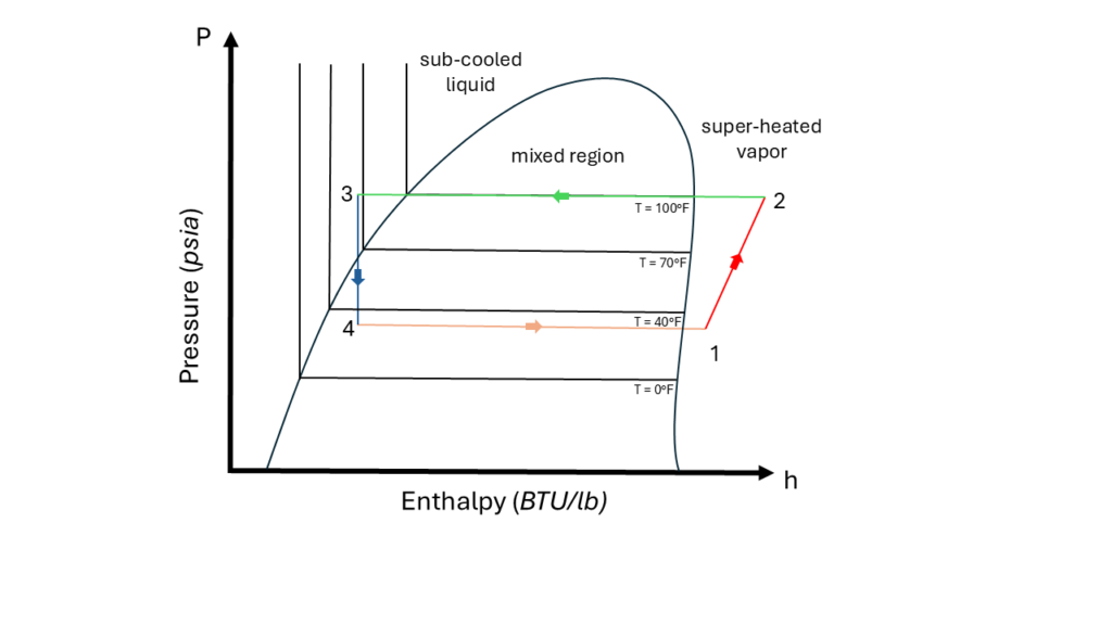
However, within the saturation curve temperature remains constant with the pressure as enthalpy increases or decreases. The evaporator has the lowest operating pressure and temperature in the refrigeration cycle, with the inlet and outlet points represented by state points 1 and 2, respectively, in Figure 3. The evaporator acts as a heat exchanger with the building’s chilled water system, such that as refrigerant enters the evaporator it absorbs heat from the chilled water system, resulting in the refrigerant becoming a vapor as it leaves the evaporator.
In a perfect refrigeration cycle, state point 2 falls exactly on the saturation curve, but to protect the compressor from unwanted liquid, the state point is usually designed to be “super-heated” into the vapor region of the graph. After the evaporator, the vaporized refrigerant enters the compressor, where work is added to the cycle to increase the vaporized refrigerant’s pressure and temperature to state point 3. At this elevated temperature, the refrigerant enters another heat exchanger called the condenser where heat is taken out of the refrigerant and absorbed by the condenser water loop.
At the outlet of the condenser, the refrigerant is a high-pressure liquid. Like state point 2, in a perfect refrigeration cycle, state point 4 would fall on the saturation curve, but typically the refrigerant is “sub-cooled” past the saturation curve to ensure only liquid is sent onward in the cycle. The last device, the expansion valve, reduces the pressure and temperature of the refrigerant back to state point 1 to start the cycle over again.
Chiller compressor types and function
There are several different types of compressors that can be used within a water-cooled chiller. Within the HVAC industry, the four most common types of compressors are reciprocating, scroll, screw and centrifugal. Each compressor type has a unique way of compressing the refrigerant vapor.
- Reciprocating compressors use pistons for compression and are best suited for small tonnage applications typically 200 tons or less.
- Scroll compressors operate by rotating two interlocking spirals and are generally best for small tonnage applications — 200 tons or less — where a quieter operation is desired.
- Screw compressors use two interlocking helical screws and are best suited for medium to large tonnage applications ranging 100 to 500 tons.
- Centrifugal compressors operate by rotating the vapor with an impeller at high speeds to increase the velocity, which is then sent through a diffuser that slows down the vapor and increases the pressure. Centrifugal compressors are generally most appropriate for large tonnage applications that are 300 tons and greater.
All of these compressor types, except for certain magnetic‑bearing centrifugal compressors, which use magnetic fields to levitate the rotating shaft and therefore operate without traditional oil‑lubricated bearings, require constant oil lubrication mixed with the refrigerant vapor to prevent mechanical damage.
Some of the fundamental functions of oil in a compressor are to lubricate the moving parts, seal gaps in the compressor between high- and low-pressure areas and absorb heat created by friction. In the compressor, the oil is sprayed into a fine mist, which is carried along with the high-pressure refrigerant vapor, eventually entering the condenser and mixing with the refrigerant liquid as the refrigeration cycle continues.
Oil in standard commercial refrigerants is miscible at higher temperatures, but as the temperature drops, oil and refrigerant are likely to separate. In addition, oil does not vaporize at the same temperatures as common refrigerants, meaning as the refrigerant vaporizes in the evaporator, the oil will remain a liquid.
If no means of oil return is implemented, the liquid oil will then sit in the evaporator and not return to the compressor. This will not only cause a reduction in heat transfer at the evaporator, but it will also cause the compressor to fail due to low oil. To prevent this, chillers are designed with oil return systems to capture the oil and return it to the compressor (see Figure 4).
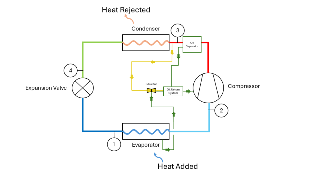
Oil return systems vary depending on the manufacturer, but in general an oil separator is used at the outlet of the compressor to capture most of the liquid oil in the refrigerant vapor. The oil is then collected from the separator, cooled or heated to maintain proper temperature and then typically pumped through a filter back to the compressor.
However, oil separators are never 100% efficient, so some oil will still move through the components and reach the evaporator. If no solution to returning oil from the evaporator is implemented, then overtime the low oil issue described above will occur.
A common method to return oil from the evaporator is done by leveraging the pressure difference between the condenser and the evaporator. To do this, a small amount of high pressure-refrigerant vapor from upstream of the condenser is passed through an eductor, which is a venturi-style nozzle that also has a connection to the low-pressure evaporator. When the high-pressure vapor passes through the eductor, the venturi effect provides suction on the line connected to the evaporator. The oil then travels through this line and is combined into the oil return system.
Operational pitfall: head pressure
A key operational challenge for water‑cooled chillers during seasonal low‑load conditions is maintaining adequate head pressure, particularly as condenser‑water temperatures drop in winter. Most water‑cooled centrifugal chillers are designed with a minimum entering‑condenser‑water temperature requirement, which ensures the chiller maintains sufficient lift, the pressure difference between the evaporator and condenser, to properly move refrigerant through the cycle.
When condenser‑water temperatures fall below this minimum threshold, the chiller may struggle to maintain the necessary pressure differential, leading to unstable refrigerant management, reduced capacity, erratic compressor loading, or even nuisance safety trips. In extreme cases, excessively low condenser‑water temperatures can cause refrigerant migration, premature surge conditions or evaporator temperature collapse, all of which jeopardize reliable chiller operation.
For these reasons, careful control of cooling‑tower fan speed, condenser‑water flow and any applicable bypass strategies becomes essential during winter and other low‑load periods to keep the condenser‑water temperature within the chiller’s allowable operating envelope and maintain stable, efficient performance.
As pressure and temperature are directly related within the saturation curve, lift can be defined as the difference between entering condenser water temperature and leaving chilled water temperature. If a chiller is used for comfort cooling in a building, the capacity and lift will generally be sized for a peak summer cooling condition.
However, in actual operation for most of the year, the chiller will be in a part-load condition. For example, when the outdoor air temperature decreases, there is less heat gain through the building envelope, so the load on the evaporator from the building decreases.
Meanwhile, the ambient wet bulb temperature will also likely decrease, causing the condenser water supply setpoint through the cooling towers to decrease proportionally with it. A lower condenser water supply temperature lowers the overall lift the chiller needs to achieve. A reduction in lift corresponds to a reduction in pressure differential between the evaporator and condenser, meaning the amount of work the compressor is required to add to the system can significantly decrease (see Figure 5).
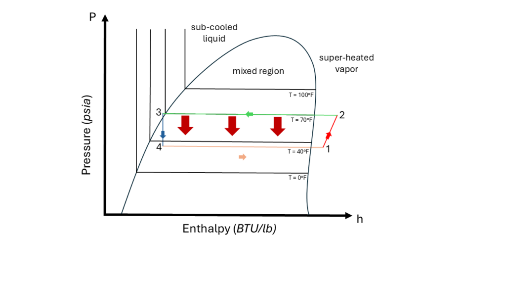
The reduction will increase the energy efficiency of a chiller until a point where the head pressure is not sufficient to keep the refrigerant flowing from the condenser to the evaporator. At this point, the refrigerant may become unstable and flow backwards through the refrigeration cycle, which can cause significant damage to the compressor.
Another issue that can be caused by low head pressure is insufficient oil return to the compressor. Many chiller designs rely on the pressure differential between the evaporator and condenser, as described above, to return accumulated oil in the evaporator. When the condenser pressure begins to decrease too far, the vapor sent to the eductor will not be sufficient to create enough suction. Without suction, the oil will begin to accumulate in the evaporator and cause the chiller to shut down to protect the compressor from damage.
Operational pitfall: low load
In tandem with issues related to condenser water and head pressure control, maintaining enough load on the evaporator side of the refrigeration cycle is crucial to prevent damage to the chiller. If the evaporator is in a low load condition, the refrigerant does not pick up enough heat to fully vaporize at the design pressure, which can cause the operating pressure and associated temperature in the evaporator to drop below freezing (32°F) to achieve full vaporization. At this point, the chilled water entering the chiller will begin to freeze upon contact with the coils in the evaporator and prevent any heat from being exchanged, causing the refrigerant to remain a liquid. When this occurs, the chiller will shut down to prevent damage to the compressor due to insufficient refrigerant flow from the evaporator.
For example, Figure 6 depicts a 300-ton water-cooled chiller that is designed to handle comfort cooling and electrical room loads. The electrical room cooling loads are calculated to be 30 tons, the chilled water to the building supplies 720 gallons per minute (gpm) at 45°Fwith a 15°F differential and the condenser water to chiller is supplied 900 gpm and 85°Fwith a 10°F differential.
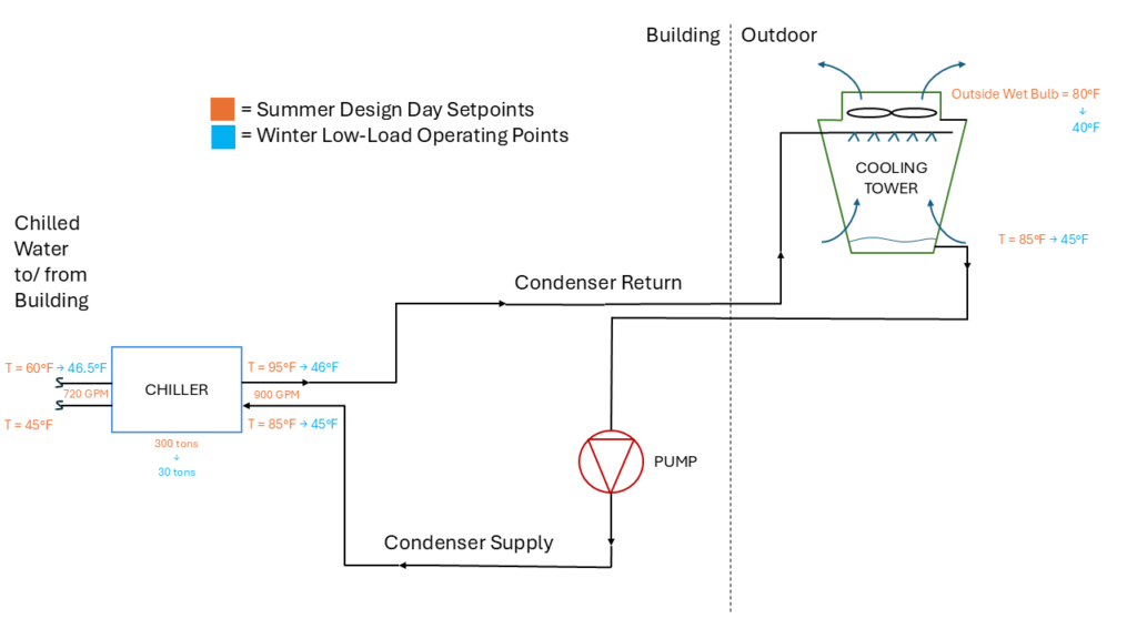
During late fall or early spring, represented in Figure 6 as blue state points, it is likely that the only cooling load remaining on the chiller would be the electrical rooms, which is 10% of the overall load. At this low-load condition, the amount of heat rejected to the evaporator from the building may be insufficient to prevent freezing of the evaporator coil. Even without the evaporator freezing, if the condenser water flow and cooling tower airflow remain constant, the condenser water will continue to reject heat at the same rate, despite the low evaporator load.
Considering this, the condenser water supply temperature will quickly drop from 85°Ftoward the low-ambient winter wet bulb temperature. Generally, if the lift reaches 15°F or less, in this case when the condenser water temperature reaches 60°F, issues due to low head pressure will start to occur.
A solution to protecting the evaporator in the low-load scenario described is to select a chiller with a hot gas bypass function. The availability of hot gas bypass should be coordinated with the manufacturer before specifying this approach.
Hot gas bypass is an additional component in the refrigeration cycle that allows artificial loading of the evaporator when there are low loads from the building. When hot gas bypass is enabled, the compressor will respond to the artificial load and consume more energy than what would be required to meet only the building load. The hot gas bypass is a connection between the compressor and inlet of the evaporator by means of an automatic or manual pressure reducing valve (see Figure 7).
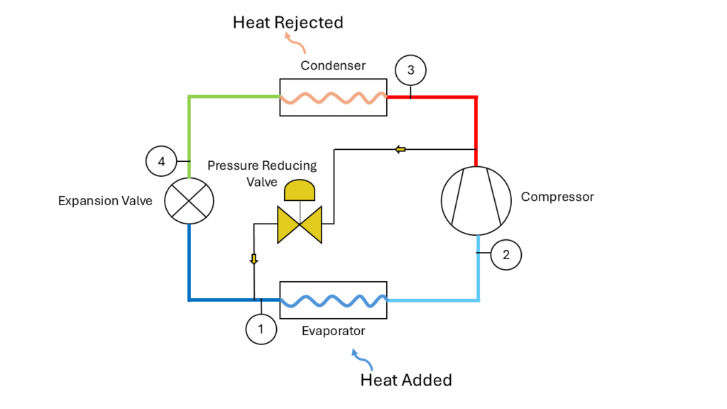
The pressure reducing valve is designed to provide constant pressure to the inlet of the evaporator, artificially increasing the evaporator’s overall pressure and temperature to a stable operating condition. This allows the chiller to satisfy low building loads by bypassing some of the work added to the system by the compressor directly to the evaporator.
However, with this solution the lift and head pressure control on the condenser side becomes a critical issue as even less heat is sent to the condenser to be rejected by the cooling towers.
Methods for chiller head pressure control
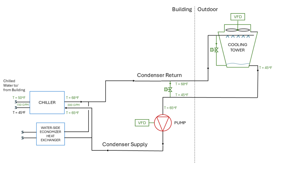
There are several solutions to maintain head pressure control in a chiller and effective control comes from careful consideration of how the condenser water system operates (see Figure 8). If the cooling towers are designed with variable frequency drives (VFDs), then as the ambient wet bulb temperature decreases, the cooling tower fan speeds can reduce to limit the airflow through the tower. With less air to evaporate into, the condenser water will reject less heat than on the design summer day.
However, at some point, any amount of airflow through the cooling towers may still cause too much heat rejection to match a low building load condition. To further reduce unwanted heat transfer, the condenser water pumps are recommended to be designed with VFDs to reduce the condenser water flow to a specified minimum.
This minimum flow should be coordinated with the chiller manufacturer’s prescribed minimum flow rate. Manufacturers will dictate minimum flow rates through the condenser to ensure that water remains turbulent and not laminar through the coils. Laminar flow greatly decreases heat transfer in a heat exchanger and may cause insufficient condensation of refrigerant, leading to negative impacts on the refrigeration cycle.
In addition to VFDs, incorporating two condenser water bypasses with motorized valves provides full control of the condenser water supply setpoint and, therefore, lift. The first bypass recommended is around the cooling tower and directly into the cooling tower basin. When this bypass is active, the tower fans can be off, allowing the water to be diverted directly to the basin to exchange relatively small amounts of heat through conduction with the cold outside air. This bypass helps limit heat transfer but still does not give the system complete control over the condenser water supply temperature.
For example, during a system start up, condenser water that has been sitting stagnant in a cooling tower basin and exterior piping will likely be close in temperature to the ambient outdoor conditions. If it is 55°F outside and the condenser water system is enabled, the cooling tower bypass will not be able to prevent the 55°F condenser water from entering the chiller before it has reached stable operation.
Most centrifugal chiller manufacturers guarantee limited operation — typically less than 15 minutes — in inverted mode, which is a temporary condition in which the condenser‑water temperature falls below the chilled‑water temperature while the chiller is operating. When this happens, refrigerant flow can become unstable due to issues with head pressure.
Inverted mode is not only predictable but expected during the transition from waterside economizer to mechanical cooling and modern building automation system (BAS) sequences are designed to manage it. Typically to manage this head pressure issue, a second condenser-water bypass between the supply and return, commonly found inside the mechanical room, is recommended. During switchover, the condenser‑water bypass valve is commanded fully open, while all cooling‑tower motorized isolation valves are driven fully closed. This strategy minimizes the volume of excessively cold condenser water that the chiller must warm up by limiting it to the water contained only within the indoor mechanical room piping, rather than the entire cooling tower loop.
By reducing this thermal mass, the entering condenser water temperature rises more quickly, allowing the chiller to reestablish proper lift and exit inverted mode safely. Without such control, the chiller would struggle to maintain the necessary head pressure, significantly increasing the risk of liquid refrigerant flooding back into the compressor, leading most chillers to shut down automatically to prevent damage.
Designing a high-performance water-cooled chiller plant requires a holistic approach that anticipates all operating scenarios, from peak summer loads to the most challenging off season low-load conditions. All major equipment, including chillers, cooling towers, pumps and heat exchangers, must be sized for both maximum demand and stable, reliable operation at minimum anticipated loads and ambient temperatures.
Reliable chiller operation depends on precise head pressure and lift control, achieved with VFDs on tower fans and pumps and proper minimum flow rates. Robust bypass and isolation valve strategies are essential for managing transitions, especially during economizer switchover and inverted mode, while ensuring the BAS anticipates and limits time in these conditions. Hot gas bypass and continuous BAS monitoring are critical for low-load safety. Lastly, all control sequences must be thoroughly commissioned and validated under simulated low-load and low-ambient scenarios to ensure reliable, year-round performance.