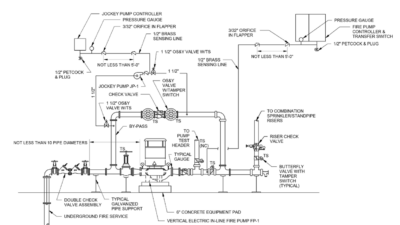
Fire hydrant flow testing provides an overview of the water supply and availability within a public distribution system, with test data used to guide fire departments when developing response strategies and drive decision-making regarding fire protection and other engineering disciplines.
Learning objectives
- Understand the fire hydrant flow testing process.
- Know the key reasons to conduct fire hydrant flow testing.
- Learn how to analyze flow test results.
Fire hydrant flow testing insights
- Fire hydrant flow testing provides the empirical foundation for fire protection design, translating measured static, residual and Pitot pressures into defensible water supply curves that guide code compliance, system sizing and risk reduction.
- Beyond fire protection engineering, hydrant flow test data inform multidisciplinary decisions from civil main sizing to structural pump loads and can uncover hidden infrastructure changes that directly affect system reliability.
Buildings and facilities served by public or private water distribution systems require a fundamental component of fire protection and water infrastructure design — fire hydrant flow testing. Hydrant flow testing is routinely required where an underground water distribution system exists, to establish the available water supply for fire sprinkler systems, standpipe systems, fire hydrants and manual firefighting operations. The data obtained from these tests form the empirical basis for evaluating system feasibility, regulatory compliance and overall fire protection reliability.
Fire protection engineers and contractors rely on hydrant flow testing to assess whether the existing water supply can support the required fire protection demands under emergency conditions. Plumbing and civil engineers use the results similarly to design underground mains, hydrant laterals and building services that supply both fire protection and potable water systems. Because water supply characteristics directly influence hydraulic performance, hydrant flow testing represents a critical early input to engineering design and project decision-making.

Hydrant flow testing is also considered during plan review, permitting and acceptance testing to demonstrate that minimum fire flow and pressure requirements are satisfied. When properly performed and interpreted, flow testing provides a defensible, real-world assessment and validation of water system performance that cannot be replicated through theoretical calculations alone.
Fire hydrant flow testing codes and standards
NFPA 13: Standard for the Installation of Sprinkler Systems specifies the primary standard governing water supply requirements for fire sprinkler systems. Additional NFPA standards establish water supply criteria for residential sprinkler systems (NFPA 13R and NFPA 13D), standpipe and hose systems (NFPA 14: Standard for the Installation of Standpipe and Hose Systems) and specialty suppression systems such as foam-water and water mist systems. Each standard relies directly or indirectly on accurate knowledge of available water flow and pressure.
Although final system demand is determined through detailed hydraulic calculations, factors such as anticipated hazards, required discharge densities, minimum end-head pressures, elevation changes and pipe friction losses allow designers to estimate water supply needs early in the design process. Hydrant flow testing refines these estimates by providing measured values that reflect actual system performance.
Some buildings and facilities are not required to be equipped with a sprinkler system. However, both the International Fire Code (IFC) and NFPA 1: Fire Code establish minimum water supply requirements for manual firefighting operations. These requirements are generally based on construction type, fire area, occupancy classification and required fire flow duration. In these cases, hydrant flow testing provides the data necessary to determine whether the available water supply can support firefighting operations without reducing system flow and pressure below acceptable thresholds.
Role of fire hydrant flow testing in engineering design
Accurate water supply data are essential for determining the proper sizing of fire protection system components, including underground piping, fire pumps, backflow preventers, control valves and system risers. Civil engineers rely on hydrant flow test results to size distribution mains and service connections supplying hydrants and buildings, while plumbing engineers use the same data to evaluate domestic and process water demands.
Errors or uncertainty about available flow and pressure assumptions can have significant consequences. Underestimating available supply may lead to unnecessary fire pumps or storage tanks, thereby increasing construction and operational costs. Overestimating supply can result in systems that fail to deliver required performance during an emergency. Hydrant flow testing therefore serves as a critical risk-reduction tool by grounding hydraulic design in measured field conditions rather than assumptions or historical records.
Fire hydrant flow testing standards and methodology
Governing standard: The primary reference for hydrant flow testing procedures is NFPA 291: Recommended Practice for Fire Flow Testing and Marking of Hydrants. Flow testing determines the available water supply at a specific location and time and identifies potential system deficiencies, such as excessive friction loss, partially closed valves or constrained distribution mains.
Flow testing does not establish absolute system capacity under all operating conditions. Instead, it provides a brief overview of system performance that must be interpreted within the context of known variability, including changes in demand, seasonal usage patterns, infrastructure condition and operational controls.
Courtesy: CDM Smith
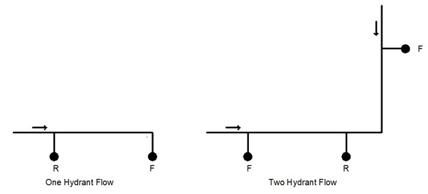
Test configuration: A typical flow test involves at least two hydrants:
- One test hydrant for taking pressure measurements
- One or more flow hydrants for discharging water to create flow conditions
The test hydrant is generally located upstream of the flow hydrant(s) to ensure that measured pressures reflect overall system behavior rather than localized losses (see Figure 1).
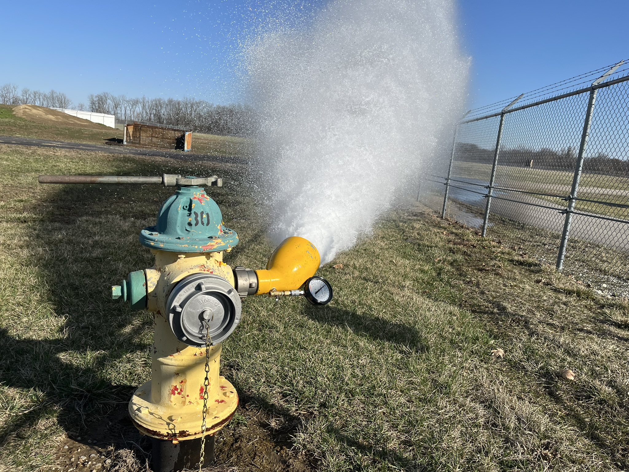
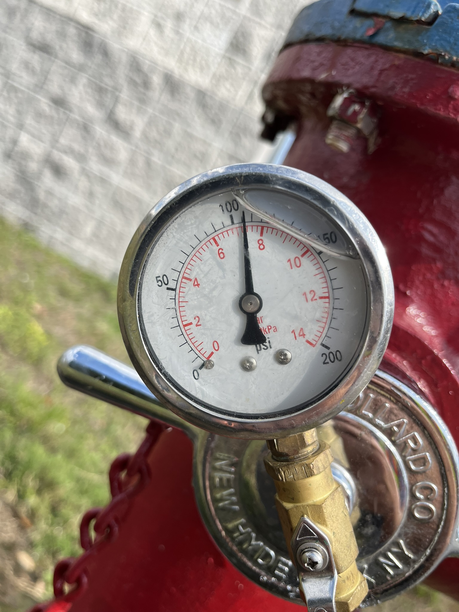
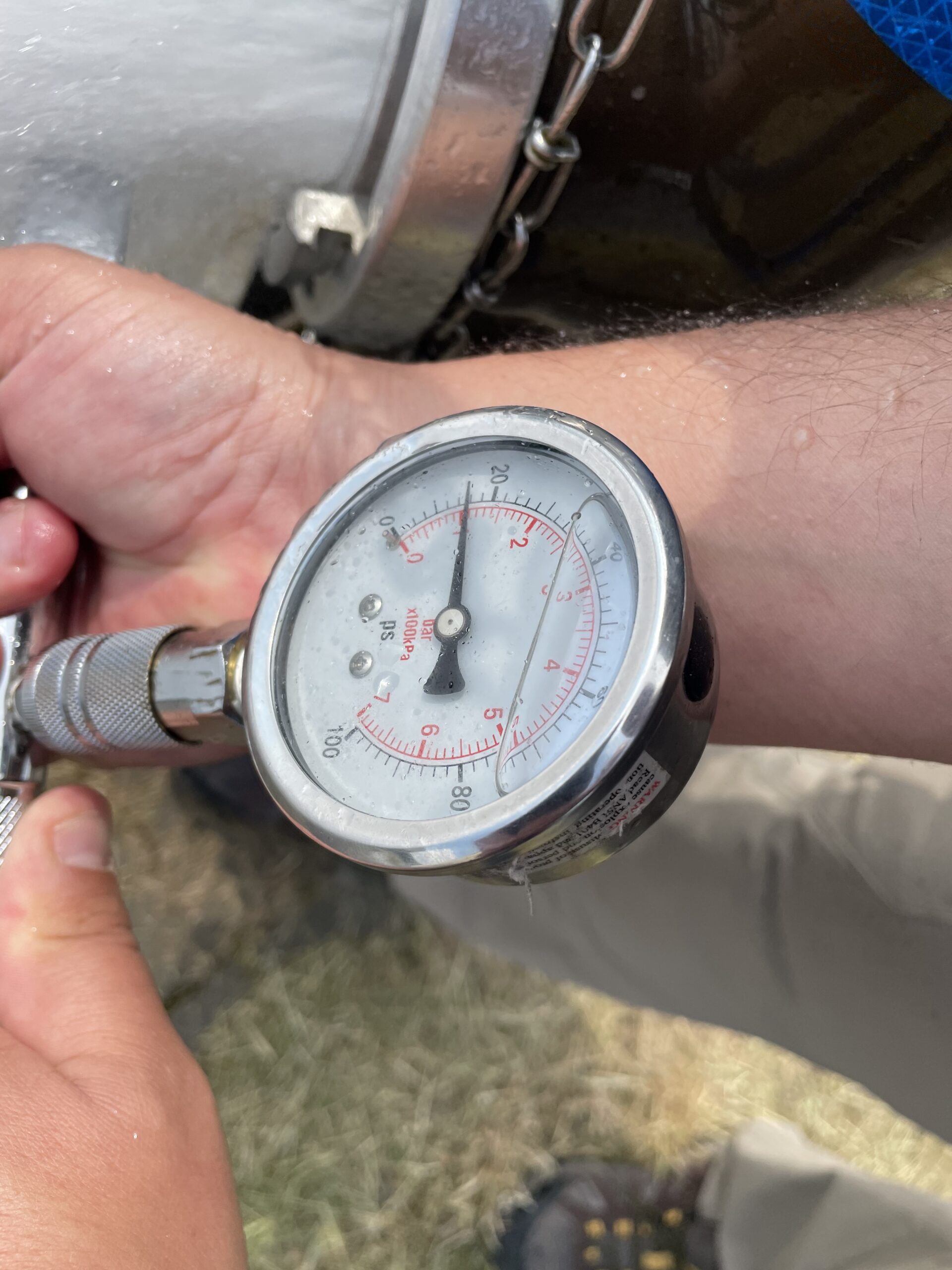
Test procedure: The procedure begins by attaching a calibrated pressure gauge to the test hydrant to measure static (nonflowing) pressure. One or more flow hydrants are then fully opened and a Pitot gauge or calibrated flowmeter is used to measure nozzle pressure at the point of discharge. While water is flowing, the residual (flowing) pressure is recorded at the test hydrant.
Courtesy: CDM Smith
Flow is calculated using the NFPA 291 equation:
where Q is the flow rate in gallons per minute (gpm), C is the discharge coefficient accounting for outlet geometry and friction loss, d is the nozzle diameter in inches and p is the Pitot pressure in pounds per square inch (psi).
Available flow at 20 psi residual pressure: NFPA 291 provides a standardized method for estimating available flow at a residual pressure of 20 psi. This pressure is widely accepted as the minimum residual pressure at hydrants for effective firefighting operations and is generally the lowest pressure to which water purveyors permit the system to be drawn during emergency use.
Calculating available flow at 20 psi allows engineers to compare measured supply against code-required fire flow and system demand under consistent conditions (see Table 1).
Table 1: Example hydrant flow test results and calculated fire flow
| Parameter | Value |
| Static pressure | 70 psi |
| Residual pressure | 50 psi |
| Pitot pressure | 25.9 psi |
| Calculated flow | 1,380 gpm |
| Estimated flow at 20 psi | 1,476 gpm |
Table 1: Values shown are illustrative only based on a 4-inch diameter and discharge coefficient of 0.57. Calculated flow depends on nozzle size, discharge coefficient and measured Pitot pressure. Courtesy: CDM Smith
Interpretation and engineering judgment
Hydrant flow test results are typically used to develop water supply curves that relate flow to residual pressure. These curves are compared against system demand curves during hydraulic analysis to determine whether the available water supply meets or exceeds required fire protection demands (see Figure 2).
Engineering judgment is required when interpreting test results. Flow test data must be evaluated in the context of expected operating conditions, including peak domestic demand, seasonal variability, storage tank levels and pump operating modes. Where required by the authority having jurisdiction (AHJ) or water purveyor, additional safety factors may be applied to account for uncertainty, aging infrastructure or future system modifications.
Engineering disciplines benefiting from fire hydrant flow test data
While hydrant flow testing is predominantly associated with fire protection engineering, the data obtained from these tests are valuable to multiple engineering disciplines involved in building and infrastructure design.
Civil engineering: Civil engineers use hydrant flow test results to size water distribution mains, evaluate system capacity for future development and assess the adequacy of existing infrastructure. Degrading test results over a period may reveal deteriorating pipe conditions as well. Flow and pressure data support decisions related to pipe diameters, looping strategies and redundancy in municipal or private water systems. In land development and campus planning projects, flow testing provides empirical input for determining whether off-site water system improvements are required.
Plumbing engineering: Plumbing engineers rely on water supply data to evaluate domestic water pressure availability, booster pump requirements and pressure zoning strategies in multi-story buildings. Hydrant flow testing helps identify whether domestic systems can operate without excessive pressure loss during fire events and informs coordination between fire protection and potable water systems sharing common supply piping.
Structural engineering: Although structural engineers do not directly design water systems, hydrant flow data can influence structural design decisions related to fire protection infrastructure. The need for fire pumps or large on-site water storage tanks affects equipment loads, flooring penetrations, seismic bracing and foundation design. Early knowledge about water supply limitations allows these considerations to be integrated more efficiently into the structural design.
Mechanical engineering and process design: Within industrial, laboratory and utility facilities, mechanical and process engineers use water supply data to assess whether available flow and pressure can support cooling systems, process water demands or emergency deluge systems. Hydrant flow testing provides baseline data for evaluating simultaneous demand scenarios involving fire protection and critical process systems.
Urban planning and infrastructure management: For municipalities and large property owners, hydrant flow test results contribute to broader infrastructure management efforts. Planners and asset managers use the data to prioritize capital improvements, evaluate system resilience and support long-term growth planning. When integrated into hydraulic models, flow testing results enhance confidence in planning-level analyses.
Coordination, safety and documentation
Hydrant flow testing must be coordinated with the water purveyor and AHJ to minimize service disruptions and pressure effects on adjacent users. Testing activities require careful planning to address traffic control, erosion prevention and safe discharge of high-velocity water.
All test results should be thoroughly documented, including hydrant locations, test dates, equipment used, measured pressures, calculated flows and ambient conditions. In some jurisdictions, hydrants must be marked or color-coded (based on performance characteristics) in accordance with NFPA 291 or local amendments.
Fire hydrant flow testing: Modeling, timing and frequency
Measured flow test data provide a valuable basis for validating and calibrating hydraulic water distribution models. By comparing modeled predictions with measured results, engineers can adjust assumptions to better reflect real-world system behavior. Validated models support future development planning, infrastructure upgrades and long-term capital improvement programs.
Conducting hydrant flow testing early in the design process improves coordination among fire protection, civil, plumbing and structural disciplines. Early identification of water supply constraints allows for informed design decisions before detailed layouts or contractor procurement begin. This approach improves bid quality, reduces change orders and leads to more predictable project results.
NFPA 13 also requires another hydrant flow test within 12 months of the submission of shop drawings of a fire sprinkler design to confirm fire flow supply adequacy, if the initial hydrant flow test was conducted earlier than the 12-month threshold.
In addition to project-specific testing, many water purveyors perform periodic hydrant flow testing as part of system maintenance programs. Engineers should verify the age and applicability of available test data, as system conditions may change significantly over time.
Fire hydrant flow testing is a critical component of fire protection and water system design that provides empirical data about available flow and pressure under real-world conditions. Accurate and properly interpreted test results support code-compliant, reliable and cost-effective design of sprinkler systems, standpipes, hydrants and potable water infrastructure.
Beyond fire protection engineering, hydrant flow test data support informed decision-making across multiple engineering disciplines, including civil, plumbing, structural and mechanical engineering. When conducted in accordance with NFPA 291 and integrated early into the design process, hydrant flow testing provides a robust technical foundation for resilient and coordinated infrastructure design.