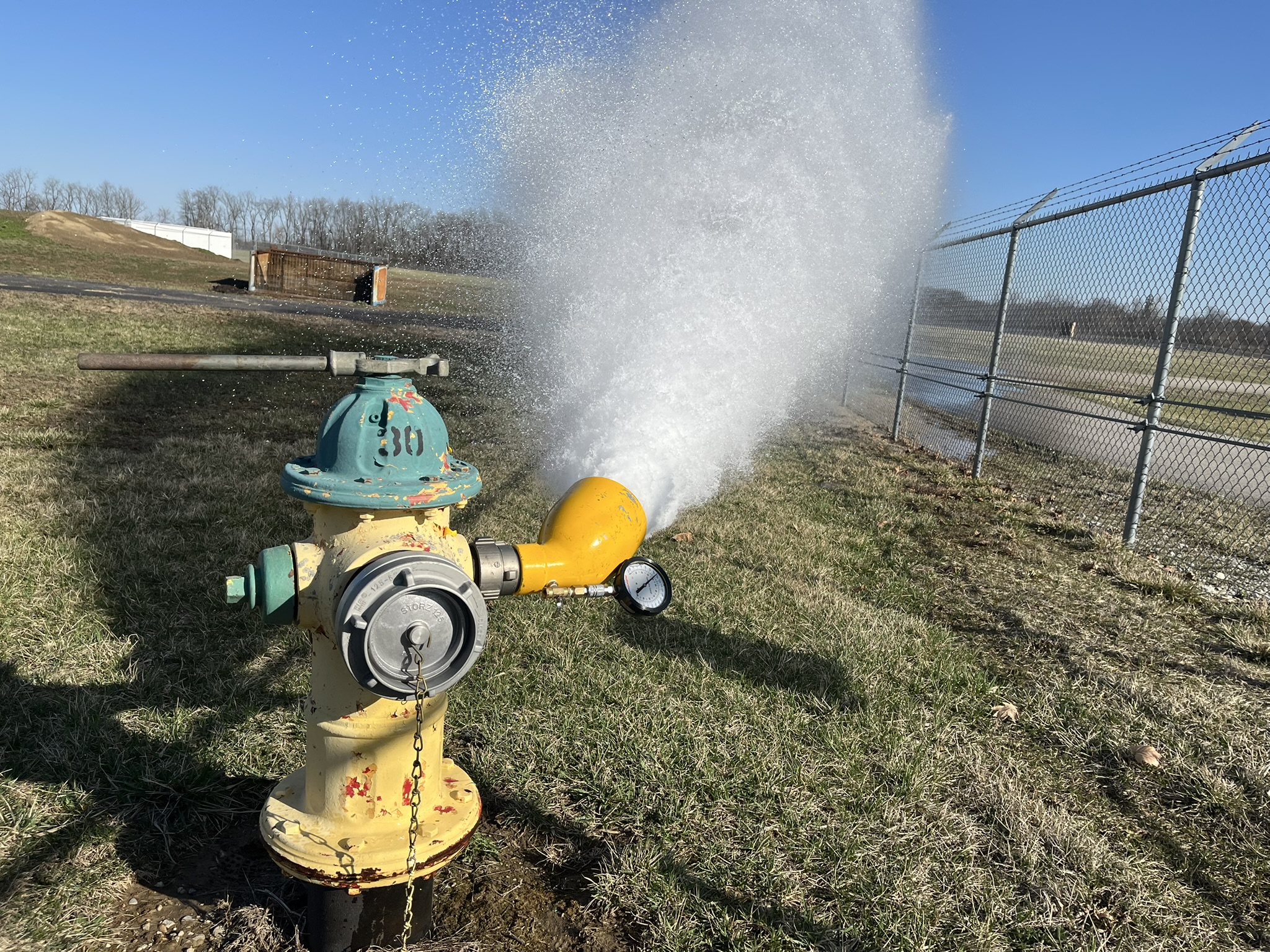
Fire pumps and their controllers are essential components of fire suppression systems when available water supply pressures are insufficient to meet system demands.
Learning objectives
- Identify common challenges associated with selecting fire pumps and their controllers.
- Understand the applicable codes and standards governing fire pump installation.
- Recognize the key components and typical layout of a fire pump room.
Fire pump insights
- Proper fire pump selection requires early coordination of water supply conditions, suction pressure and room layout to avoid cavitation, code conflicts and costly redesigns.
- Meeting NFPA 20 and NEC Article 695 requirements demands careful planning of controllers, power connections and dedicated pump-room access so systems remain reliable during emergencies.
Fire pumps and their controllers are required for a variety of fire suppression systems that fire protection engineers may encounter. Typical cases where a fire pump is required mainly includes when the fire suppression system design pressure (at design flow) is larger than the available supply pressure and flow. This can result from high-hazard occupancies including storage, large-footprint buildings, tall buildings, low municipal water pressure at the building entrance or no municipal water supply.
Sizing and selection of a pump, controller and all the accessories in the fire pump assembly is a vital task for a fire protection engineer to complete.
Codes related to installing fire pumps and controllers
Building codes: Collaboration with the authority having jurisdiction (AHJ) and reference to applicable codes and standards are the first places to start. Typically, the project’s state fire code adoption section sets the year of the International Building Code to be used. Depending on the jurisdiction, there may be amendments to the adopted code. All state and local codes must be followed, defaulting to the most stringent requirements. In the jurisdictional building code, there will be reference to the adopted version of NFPA 1: Fire Code.

NFPA 20: NFPA 20: Standard for the Installation of Stationary Pumps for Fire Protection is the foundational standard governing the installation of stationary fire pumps. It establishes minimum requirements for pump selection, sizing, installation practices and testing so that fire protection systems receive the necessary flow and pressure during a fire event. Ultimately, this standard provides the minimum requirements that engineers, contractors and AHJs rely on to ensure fire pump systems perform as intended during an emergency.
NEC: NFPA 70: National Electrical Code (NEC), particularly Article 695, is significant to fire pump installations because it establishes the minimum electrical requirements needed to ensure that fire pumps receive a highly reliable and uninterrupted power supply, even under fault or emergency conditions. Article 695 specifically prioritizes pump operation over conductor protection, requiring that fire pump motors continue running regardless of overload concerns. NEC also defines acceptable power sources, wiring methods, disconnecting means and reliability criteria, ensuring the fire pump’s electrical supply can carry locked‑rotor and full‑load currents without tripping or interruption. NEC forms the electrical design backbone that supports NFPA 20’s fire pump installation requirements.
Design challenges with fire pumps
Types of fire pumps: Fire pumps fall into a few distinct configuration categories, each selected based on the available water supply and system design needs. While electric motors and diesel engines are the two primary power sources for fire pumps, the pumps themselves come in several forms, including horizontal split-case, end‑suction (centrifugal), multistage multiport, inline, vertical turbine and positive displacement pumps.
In general, vertical turbine fire pumps are used when the water source is located below the pump, such as a cistern or a tank, making these pumps ideal for drafting water from below the fire pump. Horizontal pumps, by contrast, are used when the water supply is adjacent to or above the pump, as is typical in municipal connections or above‑ground storage and tank arrangements.
Jockey pumps are associated with a fire pump installation. They maintain pressure in the system so the associated fire pump does not need to cycle on and off. Each pump type offers unique advantages. Split-case pumps provide excellent reliability and maintainability; inline pumps offer compact installation options and turbine pumps excel where elevation or suction lift must be overcome. Together, these configurations ensure flexibility and performance across a wide range of fire protection applications (see Table 1).
Table 1: Types of fire pumps
| Fire pump type | Typical water source location | Common applications | Key advantage |
| Horizontal split-case | Adjacent to or above pump | Municipal water supplies, above-ground tanks. Larger systems with flows of more than 1,500 gpm or higher pressures. | High reliability and ease of maintenance when compared to a centrifugal pump. Diesel and electric drivers. |
| End-suction | Adjacent to or above pump | More compact than a split-case but generally limited to 1,500 gpm. More pressure than an inline pump. | Compact footprint and simplified piping. Diesel and electric drivers. |
| Multistage multiport | Adjacent to or above pump | High-rises needing multiple discharge pressures. Fewer pumps required for multiple zoned high-rise system. | High capacity with reduced floor area. Diesel and electric drivers. |
| Inline | Adjacent to or above pump | Space-constrained pump rooms, smaller systems. Lower pressure systems with flows less than 1,500 gpm. | Compact footprint and simplified piping. Electric driver only. |
| Vertical turbine | Below pump (deep source) | Cisterns, wells or tanks below pump elevation | Excellent for suction lift and deep sources. |
| Positive displacement | Adjacent to or above pump | Foam systems needing constant flows allowing accurate mixing. Lower flow and high-pressure systems. | Used for specialized systems. |
| Jockey pump | Typically the same source as the fire pump | To maintain pressure in the system under non-sprinkler-related drops in pressure, so the associated fire pump it is connected with does not cycle unnecessarily. | Requirement for all fire pump installations and prevents the main fire pump from cycling. |
Table 1: Fire pump application chart showing common applications and key advantages of different types of fire pumps. Courtesy: Fitzemeyer & Tocci Associates Inc.
Suction pressures: Suction pressure at the fire pump inlet is a critical factor in pump selection and system performance, as inadequate suction conditions can lead to cavitation and severe pump damage. Each fire pump has a listed net positive suction head that must be met to ensure stable operation without cavitation of the water entering the impeller. In field conditions, this requirement is compared against the net positive suction head available at the pump suction flange.
Selecting a pump that can operate reliably under low inlet pressure is especially important for cistern, tank and grade‑mounted storage installations, where the static water level may be adjacent to or slightly above the pump. These installations often result in minimal suction head, making long suction runs, elevation changes or friction losses particularly impactful.
Municipal water supplies typically provide sufficient suction pressure to avoid cavitation.
However, limitations can still occur during peak seasonal demand, system maintenance and other scenarios. Most municipal water supplies require that municipal sources maintain at least 20 pounds per square inch (psi) in the public water system to prevent infrastructure damage, meaning the fire pump cannot draw the municipal system below this minimum. When the available pressure falls too low to support the desired fire pump flow, the pump may experience insufficient suction head, risking cavitation or failure to meet the rated performance. Proper hydraulic evaluation including analysis of static, residual and flow test data is essential to confirm that the suction supply will consistently meet the fire pump’s operational requirements.
While there is no code-required safety factor prescribed by NFPA, insurance underwriters and some government agencies recommend and require 10 psi or a 10% safety factor on the system in its entirety. A helpful guideline is to also make sure there is a safety factor on the available water flow from the street. Another useful guideline is to not draw down the street below 22 psi to leave a 10% buffer on that supply. This allows for changes to water supply fluctuations to occur while also ensuring the system does not run out of water, especially in highly developed areas.
Space allocations and constraints: NFPA 20 requires fire pump rooms to be designed to protect the pump, driver and controller from conditions that could impair their operation during a fire event. When a fire pump is installed inside a building it protects, the pump room must be separated from the rest of the structure by a fire‑rated enclosure. The rating depends on NFPA 20’s equipment protection chapter and depends on whether the building is fully sprinklered or if the building is a high-rise. This rating helps ensure the pump and associated equipment remain operational even when the surrounding building is threatened by fire.
In fully sprinklered, noncombustible buildings that are not considered high‑hazard, NFPA 20 allows a one‑hour fire‑rated separation, but high-rise buildings or buildings not fully sprinklered require a two‑hour construction. Rooms must also be dedicated solely to fire protection equipment: no storage, heating, ventilation and air conditioning (HVAC) equipment or building electrical panels unrelated to the fire pump.
However, non-gas-fired plumbing equipment and the service may be installed in the fire pump room.
To ensure emergency personnel can reach the fire pump quickly, NFPA 20 requires that the pump room has direct, unobstructed access from the building exterior. A door that opens directly outdoors is preferred, especially for diesel‑driven installations due to ventilation and exhaust requirements.
If a direct exterior exit is not feasible, the access path must be through a dedicated fire-rated corridor with no storage or obstructions along the travel path. The goal is to allow fire departments and maintenance personnel to reach the pump quickly without passing through fire risks within the building. In many cases, especially large or critical facilities, designers provide two means of access, one from the interior and one from the exterior, to support redundancy and safety.
Fire pump rooms must provide an environment where the pump and controller can operate reliably under emergency conditions. NFPA 20 requires adequate heating, ensuring the room temperature never drops below 40°F to prevent water from freezing in the pump, piping or relief valve. Cooling and ventilation needs vary by pump type. Electric motors require sufficient ventilation to prevent overheating, while diesel pumps require more robust ventilation and combustion air supply along with safe routing of engine exhaust outdoors. The room must also maintain adequate working clearances around the pump, driver, controller and test equipment to allow serviceability. This includes clear floor space for controller doors to swing open fully and enable safe access to valves, gauges and test headers.
NFPA 20 also requires that fire pump rooms include the necessary water management and support infrastructure. This includes a properly sized floor drain or sump capable of handling packing gland leakage, flow relief discharge or pump seal water. Adequate lighting and reliable power supply must be provided, including emergency lighting when required by the AHJ.
If the pump is supplied by a tank or cistern, suction piping must be arranged to allow smooth water flow into the pump without generating air pockets or turbulence. Additional features such as test headers, flow meter loops and sensing lines must be accessible but protected from mechanical damage within the pump room or adjacent corridor.
Accessories: Fire pump accessories play a critical role in ensuring reliable, code‑compliant operation of NFPA 20 fire pump installations. Essential components include suction and discharge pressure gauges, which allow operators to monitor pump performance, as well as pressure relief valves that protect the system from over‑pressurization in accordance with NFPA 20 requirements. Flow‑measuring devices, typically a flowmeter or a test header with hose valves, enable proper acceptance testing and ongoing performance verification.
Other key accessories include eccentric suction reducers to minimize air entrapment, check and control valves on the discharge side, vibration isolation components and flexible connectors that help maintain equipment integrity. Together, these accessories support accurate pump operation, facilitate testing and maintenance and ensure the fire protection system performs as intended during an emergency.
Design challenges with fire pump controllers
Types of fire pump controllers: Fire pump controllers come in several configurations, each designed to start and operate fire pumps reliably under emergency conditions. Electric fire pump controllers are the most common and include options such as across‑the‑line (direct‑on‑line), part‑winding, autotransformer and soft‑start/solid‑state designs, all intended to manage motor starting current while meeting NFPA 20 performance requirements. More advanced installations may use variable frequency drive fire pump controllers, which offer reduced inrush current and improved electrical stability when paired with a mandatory bypass.
Diesel engine fire pump controllers provide fully automated starting, battery management and engine protection for diesel‑driven pumps, ensuring operation even when electrical power is unavailable. In addition, systems using emergency power often incorporate an automatic transfer switch controller, either as a standalone unit or integrated with the main controller, to ensure seamless transition between normal and backup power sources. Together, these controller types provide the necessary reliability, flexibility and compliance needed to support modern fire protection systems.
Electrical service connection: Typically, fire pump controllers are connected directly to the power source.
However, in some circumstances it is allowable to provide service disconnecting means and/or a transformer before the pump controller. In situation (a), the fire pump controller is installed directly to the electrical service point where no circuit breakers are located before it. When the controller is wired in this way, it is considered service equipment and the controller acts as the service disconnecting means and the overcurrent protection for the pump.
In situation (b), when the supply voltage differs from the voltage of the fire pump motor, a transformer is allowed to be installed between the disconnection means and pump controller. The transformer needs to be sized in accordance with NFPA 70 Article 695; this is noted in NFPA 20 as well. Also, there shall be no secondary overcurrent protection at the transformer.
In situation (c), when a single disconnecting means is provided ahead of the pump controller, the following conditions must be met:
- The overcurrent protective devices must be designed to carry the sum of the locked rotor current (starting motor current) of the fire pump motor, jockey pump motor and the full load current of the fire pump accessory equipment.
- Disconnecting means shall be listed for service equipment and lockable in the ON position.
- Placard shall be externally installed on disconnecting means stating, “fire pump disconnection means.”
- Placard shall be located adjacent to the pump controller stating location of the disconnection means and location of the key if locked.
- Disconnecting means shall be locked in the ON position.
Controller location: The fire pump controller is typically located in the same space as the fire pump it is serving. The controller shall be located as close as practical to the motors it controls and shall be within sight of the motors. Locating the controller outside of the space requires AHJ approval and a glazed opening to the fire pump so that pump operation from beside the controller can be confirmed. Care shall be taken to protect the controller from damage by water escaping from the pumps and installed in accordance with NFPA 20. This also includes installing the controller a minimum of 12 inches above the floor; most controllers have support legs to keep them off the floor by this distance. Note that all working clearances around the controllers must comply with the NEC.
The pump controller enclosure shall be a minimum of NEMA Type 2 enclosure or IP31. Depending on the environment the controller is in, it may require a more stringent enclosure.
Fire pump room layout
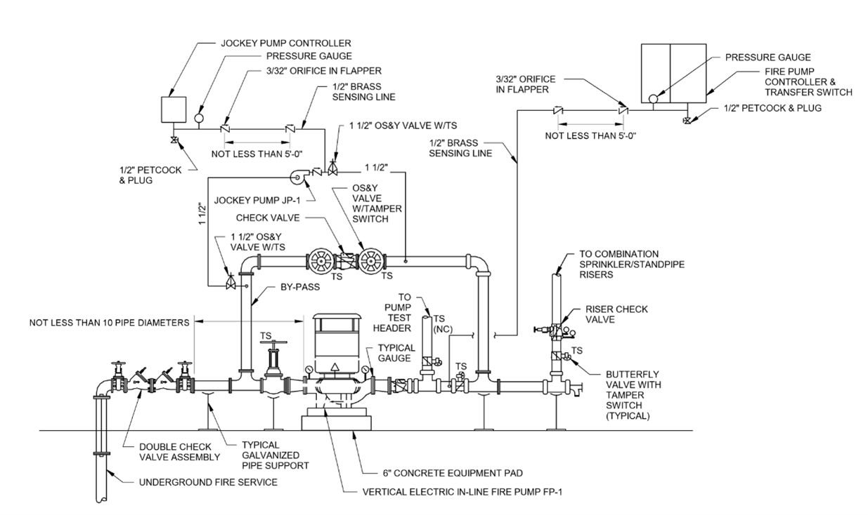
Fire pump rooms must provide adequate working space to ensure safe access, maintenance and equipment reliability as required by NFPA 20. Industry guidance and interpretations consistently reference a minimum of three feet of clearance around fire pump equipment to allow for service access and unobstructed passage. Space layout requires a minimum 3-foot-wide path through the room to the control valves, fire pump, control panel and any other piece of equipment needing access. Note that larger pumps may require more clearance and a bigger door to remove them from the fire pump room. This must be coordinated for the selected pump as the manufacturer may have requirements regarding clearance to replace a motor, pump or other defective component (see Figure 1 above).
Doors out of the fire pump room and the way to the outdoors along the path of removal need to be sized for the largest piece of equipment to be removed, which is likely the fire pump. In some cases, such as high-rise buildings, a path to the freight elevator may be used if the path to and from the elevator is wide enough. In some cases, double doors are required to remove big pumps such as large diesel pumps.
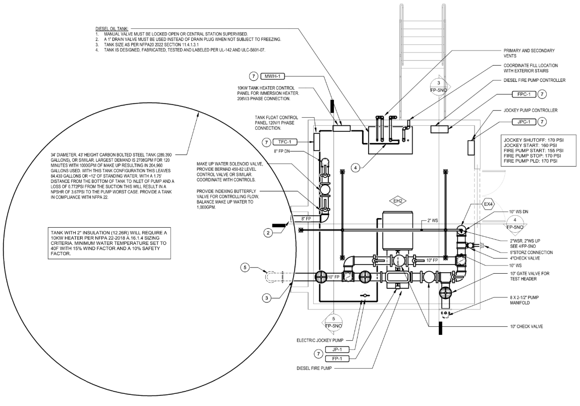
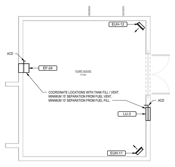
Diesel specific: Above and beyond what is required and noted above, diesel fire pump rooms have additional requirements for the diesel tanks. Clearance around the tank requires the same 3-foot distance mentioned previously along with the need for secondary containment, which is required in most applications.
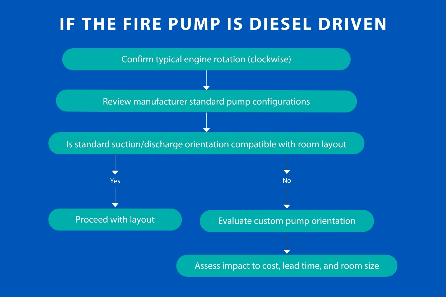
Additionally, and unlike electric fire pumps, diesel fire pumps primarily only spin clockwise (right hand) as that is the direction diesel engines turn. Something that is frequently overlooked is that custom pumps often have a counterclockwise rotation (left hand), with suction being on the left and discharge on the right when viewing from the engine side. When laying out the fire pump room, this may dictate the orientation of piping in the space to help prevent the need for custom equipment (see Figure 2).
Installation of batteries near the fire pump is something that is often overlooked as well. Note that this requires dedicated floor space and clearance. Batteries shall not be set on the floor nor within 12 inches of electrical components.
NFPA 20’s requirements for diesel exhaust are a bit limited, noting to discharge to a “safe” location. This appears intuitive to a designer, but there are a few conditions that are not apparent to some designers and can catch even experienced professionals. Combustible storage near the termination point, distance from HVAC intakes and even wind patterns can negatively affect the life safety of the building. Diesel engine exhaust requirements are noted in NFPA 20-2019 Section 11.5 with the discharge location noted in Section 11.5.3. These requirements note to “…discharge outside structure at a point where hot gases, sparks or products of combustion will discharge to a safe location.”
Water tank versus municipal supply: For water tanks such as an above-grade tank with a fire pump room adjacent to it, the room layout should be coordinated around the tank location and the make-up water entrance location. A feed from the municipal service or well will feed the tank with a bypass and check valve around the tank. The spatial requirements of these connections will dictate the room layout.
Additionally, with a cistern or water tank, level controls will be required to turn on or off the flow of make-up water. These vary in configuration but include mechanical floats that can either electronically activate make-up water through a solenoid valve or mechanically through a physical connection directly connected to the make-up water supply. A floatless valve like a diaphragm-actuated valve measures the pressure in the tank, thus calculating its fill level.
Backflow protection: Unless there is a high hazard to require additional municipal water service protection, the standard backflow preventer that is required by code is a double check valve assembly or a double check valve detector. The latter is required if the municipal service requires metering on the service. These backflow preventers can be installed in either a horizontal or vertical position, but specific manufacturer requirements must be met.
Note that higher-hazard scenarios like a glycol system require reduced pressure backflow preventers, which can only be installed in the horizontal position, causing them to take up more floor space in the water service/fire pump room.
Effective fire pump system design ensures that buildings maintain sufficient water pressure, even in high‑demand facilities or rural locations with limited municipal supply pressure. As buildings with increased combustible interiors continue to rise, it is increasingly important for engineers and building owners to make informed decisions by understanding water supply characteristics, hydraulic requirements, fire pump selection and proper installation practices. When systems are thoughtfully engineered and code‑compliant, they significantly improve reliability, enhance occupant life safety and protect property.