Innovative advancements in the plumbing industry have included high-efficiency equipment and digital systems
Plumbing insights
- Commercial building plumbing systems have improved dramatically over the past couple of decades.
- Case studies about an inline sewage ejector, corrugated medical tubing and digital hot water mixing highlight best uses for plumbing advancements.
Mechanical and plumbing engineers can help a commercial building owner save money by using more advanced systems in their design. By specifying some of the most advanced and effective equipment, long-term savings goals can be achieved.
For example, an engineer would look first at a standard duplex sewage ejector to serve a building’s waste system when the sanitary system is below the invert of the sanitary system exiting a building. The duplex ejector system is designed to efficiently remove sanitary waste from lower-lying areas to higher elevation discharge points.
A duplex sewage ejector consists of two pumps, each equipped with a float switch, check valve and motor. The pumps alternate their operation to ensure continuous and reliable sewage discharge. When the wastewater level in the basin reaches a predetermined level in the wet well, the float switch in one pump is triggered, activating the pump and starting the pumping process. The other pump remains inactive.
As the active pump starts operating it will discharge waste from the basin to the higher gravity sanitary system. The check valve prevents backflow and maintains the forward flow of sewage. The pumps must be designed to provide enough lift to allow the waste to meet the gravity system.
Once the wastewater level in the sump pit decreases below a specified level, the float switch associated with the active pump detects the change and deactivates the motor. At the same time, the float switch in the inactive pump rises, preparing it for the next cycle. For each future cycle, the roles of the pumps reverse. The previously inactive pump becomes active, while the previously active pump remains idle until the wastewater level rises again. There is also a high-water level float switch that will activate both pumps if the first pump cannot maintain the flow entering the basin.
Inline sewage ejector used as a pump alternate
Engineers have an alternative to a standard pumping system located within a wet well: An inline sewage ejector system. This type of system is a game changer that revolutionizes wastewater management by offering efficiency and convenience. Designed to handle sewage and wastewater in a wide range of settings, this technology simplifies installation, optimizes performance and reduces maintenance requirements.
An inline sewage ejector system consists of an inline ejector pump, control panel and monitoring system — all seamlessly integrated to provide reliable and efficient operation. Unlike traditional sewage ejector systems that require a separate wet well and complex set ups, an inline ejector simplifies installation with its compact design and inline installation capability.
The inline pumping system operates by means of a pressure sensor located beneath the entry chamber of the pumps. The sensor continuously measures the height of the fluid at the inlet into the pumps. The sensor consists of a stainless-steel flush membrane and is highly resistant to wear and tear. It is resistant to deposit build up because of the fluid speed coming into the pumps and the suction of the pump.
The connection from the sensor to the control panel is completed by a rated cable. In addition to the information transmitted from the sensor to the control panel regarding the inlet fluid height, information can be sent by the transmitter for remote observation of the system’s operation without the need for any additional equipment by using an isolated output of the control panel. The panel itself comes with a user-friendly display that indicates speed, intensity, level gauge, motor power, motor torque, flow meters and status readings for remote users.
The benefits of an inline pumping system include:
-
Excellent performance and efficiency. The hydraulic design ensures optimal water flow and maximizes energy consumption. The inline pump operates with minimal friction loss, thus providing a constant and reliable discharge.
-
The pumping system incorporates smart technology and control features, allowing for real-time data collection, analysis and remote adjustments to maximize operational efficiency. Measurements that can be monitored are predictive automated analysis, tuning, over torque and active factory assistance. All monitoring is globally accessible 24/7.
-
An inline pump system can replace an existing system in an existing wet well.
-
A compact and space-saving design, making it suitable for installations with limited space. The inline configuration eliminates the need for extensive infrastructure and wet wells, optimizing the use of space when the pump needs to be installed in tight mechanical rooms. This is especially beneficial in a renovation project.
-
Environmental sustainability. With the efficient operation and energy saving design, it helps reduce the carbon footprint associated with the entire system. Anticontamination features are incorporated by means of including backflow devices to ensure the safe disposal of the sewage waste.
-
The inline system is driven by variable speed drives. Operation is no longer based on “all-or-nothing” pumping but on continuous modulated pumping directly from the effluent inlet.
-
The cabinets and the control panels are delivered ready to be plugged in. Only the two motors and the sensor require connection for operating the system. All internal connections are made and tested in the factory. Dry contacts for remote surveillance status reports are fitted as standard.
-
By pumping gravity-fed effluent directly from the point of entry, without water loading or a wet well, the inline pump overcomes the drawbacks of retaining raw sewage. No dangerous gases (hydrogen sulfide, or H2S), sand and grease accumulation, structural erosion or obstructed float switches are present — the owner or maintenance personnel always have safe access. The system can pay for itself with reduced maintenance requirements.
No authority having jurisdiction approval is required with the in-line system. Engineers should also consider capital cost and coordination with the architects and civil engineers on the project.

Case study: Pump system upgrades plumbing
Submersible pump stations around the world share a common enemy, the flushable wipe, which really isn’t that flushable. In a traditional wet well system, these wipes are separated from the pumped liquid, solidify and form clogs that result in costly maintenance service calls. Inline pumping systems help eliminate the main cause, the ejector basin.
In Texas, a 23-story, 30-unit high-rise residence building with a grocery store and restaurant had continuous issues with frequent pump clogs; six clogs in a two-month timeline created costly maintenance issues for staff to remove clogs, fats, oils and grease.
The reason for the constant clogging was flushable wipes. Despite the staff notifying the building occupants on multiple occasions, they could not control what was being flushed into the sanitary system. The clogging continued and maintenance costs continued to rise. The building owner needed a solution to stop the clogging and provide the occupants with a first-class residence.
The building owner’s service team quickly removed the antiquated submersible pumps, piping, rails and control panel. With the equipment removed, the 60-inch diameter fiberglass basin was prepped for the new dry-pit system. The inline pump arrived factory pretested, pre-wired, assembled and ready to be installed.
Within 2.5 hours, the wet well was transformed into a dry pit and the inline pump installation had begun 10 feet below ground. In a safe, clean and dry environment, the team was able to connect the suction directly to the invert and construct the discharge piping. A sump pump was used with the system to handle any water ingress from the hatch. The valve vault was no longer needed and could be removed during future construction.
In just one day, the source of much pain and expense had been converted from a wet well into a dry, clean and reliable pump station.
Corrugated medical tubing meets plumbing needs
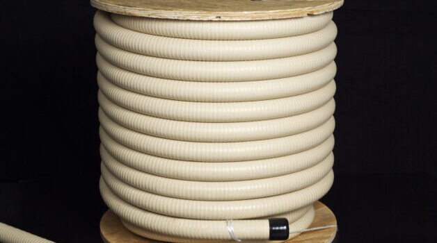
Until the 2018 edition of NFPA 99: Health Care Facilities Code, the only option for medical gas piping was seamless copper tubing that is cleaned and capped. Included in the 2018 update was the new option of using corrugated medical tubing (CMT). CMT is a semi rigid tubing made from a copper alloy. The corrugated piping allows for continuous runs without the need for fittings to provide a change in direction (see Figure 2).

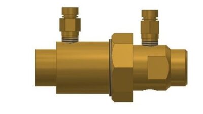
CMT is available in 0.5-2 inch sizes. The fittings to connect sections of CMT are an axial swaged, sealed quick-assembly brass fitting, which can connect sections of CMT to each other or to standard copper in case of a renovation project or a hybrid standard copper/CMT installation. CMT has rolls of piping in lengths of up to 500 feet (see Figure 3).

CMT must be installed by an American Society of Sanitary Engineering 6010: Medical Gas Systems (or state equivalent) certified installer who has successfully trained through the manufacturer’s installation program.
The benefits of using CMT when compared to seamless copper are significant. With fittings no longer required, the need for hot work is significantly reduced if not removed completely. Not only does this lessen the potential risks of fire damage but it reduces the cost of paying for a fire watch. The speed of installation and lower installation cost also make CMT a viable option. The quicker installation time for CMT will reduce the time on-site for the contractor, in turn reducing the overall cost of the project and minimize downtime for the hospital. CMT also cuts down dust and contaminants that can be harmful in a health care environment. Hangers shall be installed per manufacturer requirements and bending radii shall not exceed installation requirements.
When installing CMT below grade, there are also time and cost savings. All brazed fittings are eliminated while minimizing any potential of contamination of the system. The elimination of below-grade fittings removes the potential for points of failure. With the requirement of the inspection of underground fittings eliminated, the installation process is simplified.
Be mindful of which edition of NFPA 99 a municipality recognizes; some cities/towns require designing to an earlier version of NFPA 99 (before CMT being accepted). In this situation the Centers for Medicare & Medicaid Services can issue a waiver, QSO-20-40-LSC, which allows the installation of CMT in both new and existing applications. The waiver, introduced in 2020, requires the facility owner to document the use of CMT and that the systems were installed per NFPA 99 requirements.
Case study: CMT enhances hospital plumbing
A renovation project at a local community hospital in Massachusetts included the relocation of an existing zone valve box from the patient care area to a designated area outside of the patient care area, as required per NFPA 99.
The new zone valve box, containing shut-offs for both a vacuum and oxygen line, was located on the other side of a corridor beyond the fire stop roughly 65 feet away. For comparison purposes the vacuum line was done in 1.25-inch hard-drawn copper pipe and the oxygen lines were done in 1-inch CMT. All piping runs were done in parallel taking the same route between connection points.
Approximately 75 feet of piping was used for each run (150 feet per system). The piping run included a vertical rise out of the new zone valve box followed by a series of 90- and 45-degree bends to the 65-foot straight run down the corridor. The piping then turned 90 degrees across the corridor and was tied into the existing supply and distribution lines. Both piping systems used the same existing hanger supports down the 65-foot corridor run.
Table 1 compares the materials required for medical vacuum brazed hard-drawn copper pipe versus the CMT system.

As with all rigid piping installations, elbows are required when turning corners and changing direction to route around, above or below obstacles. CMT can bend around corners and flex to avoid potential obstacles, resulting in no intermediate connections. In this case, two 1-inch CMT lines were pulled together, much like pulling wire or cabling through a hole in the firewall down the entire length of the corridor in roughly 15 minutes. An additional 30 minutes later, the piping rough-in was complete and ready for fitting connections.
There was a significant labor savings between the installation of the brazed hard copper and CMT. The brazed hard copper was anticipated at 64 person hours to tie in the new valve box and prepare for final tie-ins, so this is not a final installation. The labor estimate for CMT installation was 12 hours to pull and make all final connections.
Overall, the use of CMT resulted in a 79% reduction in joints for the piping system and a minimum of an 82% reduction in labor hours.
Additional benefits of the system included:
-
Ease of transport to the job site.
-
Reduced cost in support items such as brazing rods and purge gas.
-
Contamination possibility was greatly reduced.
-
No need for intermediate joints due to the continuous lengths of piping.
-
The continuous lengths of piping also resolve fire prevention concerns. No brazing is required in confined spaces, unlike what is required for hard drawn copper systems.
Digital hot water mixing
Thermostatic mixing valves are used to keep water at a constant temperature by blending cold and hot water in a steady flow to assure safety while washing hands, showering and/or bathing. The primary goal of thermostatic mixing valves, which are designed to manage water temperatures, is to prevent scalding. A mixing valve allows the temperature of the water in the water heater to be increased (to lessen the risk of bacteria growth) while also preventing scalding. Plus, by combining hot and cold water, available hot water supply is more readily available.
A standard thermostatic mixing valve consists of four main parts:
-
Thermostatic element: A temperature-sensitive device that expands and contracts when the temperature of the water fluctuates.
-
Piston: The piston moves in response to the thermostatic element sensor. The piston will quickly close if the hot or cold water temperature regulation fails.
-
Return spring: The return spring of a thermostatic mixing valve pulls the piston back to its original position after it has contracted or expanded.
-
Temperature adjuster: The adjuster is used to regulate the outgoing temperature of the mixing valve by turning the external handle of the valve. A thermometer should always be installed on the discharge side of the mixing valve to determine the outgoing temperature.

Recently, there has been a move toward the use of digital mixing valves. Digital water mixing directs hot water delivery through a programmable valve or system that processes temperature, flow and pressure data. The data is obtained from the hot and cold water inlets, mixed outlet and sensors on the mixed water return. High-speed electronic actuation modulates a simple ball valve that allows the setpoint to be maintained. Fast, responsive digital technology enables the collection of a large amount of data that can be stored and communicated through a building automation system (BAS) or locally at the controller, providing intelligence at the foundation of the entire plumbing system.
Digital mixing valves place instantaneous information at an owner’s fingertips to allow for immediate decision making when safety is a concern and for operational decisions to help conserve water, perform more efficiently and reduce system downtime and the associated costs.
There are three main technology-driven components in a digital mixing solution:
-
The controller’s algorithm.
-
Sensors.
-
Cloud-based technology and mobile apps.
The benefits of a digital mixing valve include:
-
Maintains safe water temperature to prevent scalding and thermal shock.
-
Delivers consistent hot water on-demand, wherever and whenever it is needed.
-
Conserves energy through efficient water temperature management.
-
Integrates with a BAS to provide broad management capabilities.
-
Reduces repair and maintenance costs.
-
Minimizes risks and liability for owners, engineers and facility managers.
-
Eliminates the need for an aquastat.
-
Simple plug and play installation.
-
Remote access alerts enable a facility manager to see and monitor the plumbing water system(s) from anywhere.
-
Can be used for quick decision making when control of the system matters the most.
-
Digital mixing valves that have digital LED touchscreens to allow immediate hot water temperature control.
Case study: Hotel plumbing system problems fixed
Hotel staff often receive complaints about the lack of hot water; the highest use is typically early morning when guests prepare for their day. This was the case for several years at a 384-room airport hotel. The hotel would get several calls a week from guests about the lack of hot water. The best explanation that could be given was that “it was being worked on.” The hot water issues lasted for more than two years. Hotel management, along with contractors, did a deeper dive into the issue and it turned out that a large hydronic valve was used for the original domestic hot water system. It was determined the valve had a 120-second response time and couldn’t actuate quickly enough to keep up with the hotel’s changing water pressures.
Because of the valve’s longer response time, whenever something went wrong with the pumps, heat exchangers or storage tanks, the entire domestic hot water system would require a time-consuming recalibration. Maintenance was required routinely and became a constant source of disruption for the engineering staff. Once the existing valve was replaced with a digital mixing valve, the hot water issues disappeared. Thus, eliminating the costly maintenance issues along with the hotel guest complaints.
Above are just a few advancements in the plumbing design field. It is recommended that all engineers reach out to manufacturers and manufacturers’ representatives to keep apprised of new technologies and new ways of designing plumbing systems for systems to be smarter, more efficient and longer lasting.