Creating effective communication between the commissioning team and the testing, adjusting and balancing team can help streamline solutions for issues in a chilled water system.

Learning Objectives
- Understand why quality assurance is a fundamental part of the construction process that includes following the procedures outlined in the equipment and installation, operations and maintenance manuals.
- Identify the responsibilities and importance of the testing, adjusting and balancing (TAB) team during the construction project.
- Learn quicker and more efficient ways to troubleshoot issues throughout the construction process.
Chilled water insights
- Effective collaboration between different teams — including commissioning, mechanical and TAB contractors — is essential for diagnosing complex problems, emphasizing the significance of integrated efforts in ensuring optimal operation, energy efficiency and environmental comfort in building systems.
- A methodical troubleshooting approach makes it easier to diagnose and fix issues in a chilled water system.
The commissioning (Cx) team performed forensic detective work on a chilled water (CHW) system. The CHW system measurements reflected a high volume of water leaving the CHW pump and too little CHW at many individual heating, ventilation and air conditioning (HVAC) units. The water leaving the pump must equal the water circulating in a closed loop hydronic system. This does not add up, unless there is a major leak. So, where did the water go?
In addition to leaving the testing, adjusting and balancing (TAB) team unable to continue, the problem would lead to wasted energy and unstable room temperature control if left unattended.
A chilled water problem
The new five-floor residential building consisted of three floors above grade containing 302 hotel rooms. The two floors below grade consisted of a full basement and a full cellar. A five-floor core section linked the three Y-shaped buildings together, which was implemented in three project phases. Fan coils, equipped with a hydronic chilled water and that were heating hot water, supplied HVAC to each room.
The mechanical contractor installed and started the hydronic (CHW pump, tanks, valves, etc.) and HVAC equipment. The TAB team measured the CHW pump performance. Everything was fine up to this point. The TAB project scope involved differential pressure readings of the CHW automatic flow, limiting balancing valves and FLVs on the 350 fan-coil units and six air-handling units. The CHW pump differential pressure (ΔP) setpoint was set to reach a minimum of 2.0 ΔP at the FLV on the worst-case unit. This allows for efficient system operation and better room temperature control.
The CHW pump circulating the water ran at the nameplate motor amperage that indicated the pump is running as expected. However, several CHW FLVs installed on fan-coil units measured less than the minimum required pressure drop of 2.0 ΔP.

The numbers did not add up; the CHW pump performance data reflected design CHW waterflow and the fan-coil units indicated not enough waterflow.
Beginning to troubleshoot the issue
Troubleshooting does not always mean looking for a needle in a haystack. The teams started with a simple “could be/no way” list approach. This is a process where the team first cuts out options are the obvious “no way” issues and then progressively eliminates other possible issues. This process also included comparing this system to one that is working properly.
Not possible issues
-
Electrical issue? No way. This is mechanical in nature.
-
System leak? A leak would show up with water puddling on the floor or flooding. In addition, the makeup water meter would show water entering the system to makeup for water leaving the system.
Other possible issues
-
A pump rotation issue? A pump spinning backward may still show waterflow and positive pressure. The Cx team did not want to assume, so they verified the pump rotation again.
-
The hydrometer used to take the readings? The hydrometer used to measure the CHW pressure differential had a very recent calibration certification from the manufacturer. However, the TAB team used a different calibrated meter to eliminate a faulty meter from the equation.
-
Inaccurate pump performance data? To verify the waterflow determined when using the pump curve, the team used an ultrasonic strap on the meter. The flow from the ultrasonic meter and the pump curve matched within percent. In addition, the system’s flow transmitter was also within an acceptable percentage of the pump curve and ultrasonic meter.
-
Piping distribution issues? Could be. Perhaps a bypass valve?
-
Fan-coil hydronic component issues? Should the team trust the FLV pressure measurement? What issues could result from a faulty fan-coil hydronic component?
The team used the same forensic tool for the piping distribution and individual fan-coil unit troubleshooting, a differential static pressure profile.

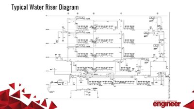
The team prepared a system piping diagram based on the mechanical drawing piping detail. The pressure readings were noted on the diagram to see the big picture on one page. The testing started by measuring the differential pressure between the return and supply pipe mains using the pipe pressure-temperature access ports. Due to installation, pressure ports needed to be installed on certain riser drain locations as a temporary measure to record the differential pressure across the riser return and supply pipes. Looking at the big picture, it added up.
The pressure drops across the fan-coil unit cooling control valve and cooling coil both showed well above design waterflow on certain units and low waterflow on other units. Why was the pressure drop across the FLV exceptionally low on these units showing above design waterflow across the cooling coil? What could cause a FLV to have above design waterflow but below design pressure drop? The challenge is how to go from “could be?” to “this is it.”
An inspection of the FLVs revealed that the manufacturer placed the flow direction sticker in the wrong direction on a batch of FLVs, resulting in the FLV being installed backward. Once the FLV reversed to the correct direction, the pressure drop reached the required 2.0 ΔP.
But the head scratcher continued. Although certain FLVs were installed in the correct direction, the pressure drops on other FLVs indicated low pressure drop with above normal pressure drop across the cooling coil. The team put the FLV under the Cx microscope by disassembling it (see Figure 1).
The rubber diaphragm is position sensitive and when installed backward or missing forces, the valve will open with flow or allow for full flow through the valve; hence the low pressure drops even with lots of water moving through the FLV. The rubber diaphragm was removed before soldering but installed backward or, in some cases, never reinstalled. The install team corrected the issue by following the FLV installation, operations and maintenance (IOM) manual install procedures to wrap the valve body with a wet rag.

Three things to know about chilled water projects
When identifying issues in a chilled water system, there are multiple places where the problem could have occurred. Three places to make sure issues don’t arise include:
-
Quality assurance is a fundamental part of the construction process and includes following the procedures outlined in the equipment and IOM manuals. The manufacturer detailed a solution to the valve soldering issue in the IOM manual. On the other hand, the misplaced FLV direction sticker was a quality control issue beyond the project.
-
TAB is indispensable during the construction project. In addition to helping with energy conservation and temperature control, TAB is a troubleshooting and mechanical system health tool. As a result, the Cx team TAB report review occurs before the functional testing phase.
-
Troubleshooting should not involve looking for a needle in a haystack. The Cx team, which included the mechanical and TAB contractors, dissected the system to narrow down the issue using actual system measurements. Viewing the system pressures at each major connection in the system and across each fan-coil component allowed the team to focus efforts on the real cause in less time.
Once it all added up, the CHW system was balanced, energy payback rebates were set in motion and the cooling system delivered stable temperature control to the spaces.