By considering updated controls architecture, integrating building systems together becomes much more attainable and streamlined
Learning objectives
- Learn about how mechanical controls architecture functions.
- Understand building lighting controls functions.
- Demonstrate the potential to integrate these systems together into a single controls network.
Commercial buildings consume nearly 36% of electricity in the United States. Mechanical systems, lighting and plug loads consume a majority of commercial building electricity. Information technology, audiovisual, security and fire systems also consume electricity to meet building demands and codes. Building energy use is managed and can be curtailed through the various control systems implemented.
Major electricity consumption through heating, ventilation and air conditioning systems are managed by the building automation system. Historically, the BAS controls mechanical systems, while lighting and plug loads are managed by separate systems, typically provided by a lighting controls manufacturer. IT, AV, security and fire systems are typically controlled by separate manufacturers.
Control requirements vary to support the project goals, comply with the codes enforced and to control building operation costs and energy consumption. Within the United States, most states adopt energy codes for commercial buildings.
The International Energy Conservation Code is recognized as code, with compliance paths through ASHRAE Standard 90.1: Energy Standard for Buildings Except Low-Rise Residential Building, currently the 2019 edition, though this edition is not accepted by many jurisdictions.
Beyond the state level, local jurisdictions and federal requirements may deviate or exceed the state adopted energy requirements. Multiple codes, versions and compliance paths governing energy use through control systems — combined with client project goals — necessitate coordination through trades to provide value to the client.
Currently, codes and requirements for mechanical controls only describe how the control system should operate and does not provide the associated sequences of operation. For instance, in the 2018 edition of the International Mechanical Code Section C403.6.5, multiple-zone HVAC systems are mandated to have automatic supply temperature reset in response to building loads or outdoor air temperature. The code then describes the requirements for the temperature reset and provides exceptions but it does not list any sequences of operation for designers to use.
Recently, ASHRAE published Guideline 36: High-Performance Sequences of Operation for HVAC Systems, which standardizes advanced sequences of operation for the use of mechanical designers and controls contractors. In future code editions, this will be referenced to provide a verified and streamlined way to write and implement new sequences of operation into different BAS architecture.
Defining the controls architecture
Typical BAS architecture is designed through building automation and controls network (BACnet) over internet protocol, referred to as BACnet/IP, at higher level BACnet building controllers with master-slave token-passing at room-level BACnet application specific controllers (see Figure 2). B-BCs generally have higher computational power than B-ASCs to run complex sequences of operation for the overall building system, which is why IP connections are used because data can be communicated much faster than with MS/TP connections.
The B-BCs then send or request data to the B-ASCs, which then, in turn, enact simpler sequences of operation on a specific device. In addition to these two levels of controllers, BACnet advanced application controllers can be used as a steppingstone between the B-ASCs and a B-BC. B-AACs are usually connected using MS/TP and provide additional computational power to the BC to run overall system sequences of operation.
B-ASCs and B-AACs that are connected on the same MS/TP trunk are daisy-chained together and can only communicate with another device by passing a “token” down the line. After a controller requests and receives a token, the controller is then allowed to open an application layer message using an application protocol data unit. This then allows the device to pass/communicate the token on to other controllers or back to the master controller. The only exception to this process is the master device, which can have the token and request or send the token without being specifically asked to.
MS/TP connections inherently add delays in communication to and from the BAS because each individual token must be passed through the chain of controllers until it finds the correct device. To prevent excessive network backup, it is best practice to place application specific controllers that receive greater traffic closer to the master controller and keep high traffic devices on separate MS/TP trunks.
Meanwhile, upstream of the B-ASCs and B-AACs, the B-BCs are connected with BACnet/IP to the main BAS. In this network, each device is assigned its own unique IP address, which allows the BAS to know exactly where each device is in the network. The IP addresses let the BAS send commands and information directly to the device in question through ethernet cables, rather than going to each device along the way like with MS/TP. BACnet/IP is not often used throughout the system architecture because of the complexity and cost of installation from programming/assigning each device with its own unique IP address.
Controlling equipment
In a typical commercial building, devices such as variable air volume boxes and fan coil units are controlled by B-ASCs (room-level controllers). These devices can handle simple sequences of operation such as maintaining temperature requirements and relaying commands from the B-AACs and B-BCs. Because B-AACs and B-BCs have the most computational power in the BAS, they perform intensive sequences like supply temperature reset, hot water reset and other overall system commands. Typically, chilled/hot water plants and larger pieces of equipment, like air handling units, have their own dedicated building controllers to handle the amount of sequences required to effectively execute commands to the system.
The building controllers also report sensing data and other computed results to an operator workstation and/or to a cloud network depending on the client’s needs. Because all sensing data must go from room-level controllers all the way up to building-level controllers and then back for some commands, the amount of traffic on a network can be extremely high. At times when multiple computationally intensive sequences are trying to be executed, delays in the network can be minutes long.
In addition to mechanical control architecture, lighting and plug load control architectures also are implemented to reduce energy consumption and the associated costs, while supporting space functions. Because illumination levels and plug load energization are critical in supporting effective space use, it is important for the control system to prioritize supporting the functions within each space and to reduce energy without impacting functionality of the space.
Codes and standards
Client-specific space use requirements are typically evaluated in conjunction with code analysis for control requirements to achieve code compliance. Lighting, control and energy codes/standards analyzed include but are not limited to:
- ASHRAE Standard 90.1.
- International Building Code.
- Illuminating Engineering Society: The Lighting Handbook, 10th Edition.
- NFPA 70: National Electrical Code.
- NFPA 101: Life Safety Code.
Each code and standard is intended to provide minimum requirements for the electrical design. The IBC and NFPA 101 provide minimum emergency egress illumination requirements. NFPA 70 contains requirements for most electrical systems and specifically addresses emergency systems within Article 700. IECC and ASHRAE 90.1 provide minimum energy-related requirements for electrical systems. IES is a reference for average and uniformity illumination targets, while also providing recommendations for various lighting applications.
The most recent energy codes are designed to consider typical space type requirements and to provide options for achieving compliance. The options provided by code allow design professionals to tailor control systems to space use goals, while ensuring energy reduction.
Where the ASHRAE 90.1-2010 edition (or more recent) are adopted, designers are required to analyze each space type and provide a variety of control methods within. In general, ASHRAE 90.1 requires user controllability through local lighting bilevel controls. While local control and bilevel control requirements vary by space, the intent is to provide user controllability within each space. Local bilevel controllability provides users opportunities to reduce electricity consumption and to customize the visual environment to support the user task. Beyond user control, most spaces are required to adjust the lighting and plug loads based on occupancy and vacancy.
Lighting and lighting controls
ASHRAE 90.1 allows for occupancy to fully energize lighting fixtures in select spaces. Many spaces are permitted to partially energize the lighting load in each space when occupancy is detected and others energize lighting loads only when initiated by a user. The code intent is to adjust light output when a space is vacated, either by fully or partially de-energizing the lighting fixtures depending on the space.
Certain spaces are permitted to allow system schedules to override vacancy and maintain illumination in vacated spaces. Nearly all spaces are required to reduce light output in determined daylight zones when daylight contributions are sufficient to support the task in the daylight zone. Plug load control requirements are generally tied to occupancy/vacancy and time schedules, with scheduled overrides to occupancy control permitted in select spaces.
To support the user, occupancy/vacancy, daylight harvesting and scheduling requirements within each space, multiple control points are required. The control points for lighting controls are often referred to as zones; it is common economical practice to share line voltage power circuit wiring across multiple spaces and zones without impacting controllability.
Within a space, multiple sensors are installed to react to user input, occupancy/vacancy status and daylight contribution. User keypads respond to user action, to energize or de-energize lighting fixtures, signal programmed scenes or adjust light output via an electrical signal. Occupancy/vacancy sensor technologies can detect ultrasonic (sound) waves within a space, passive infrared (heat) energy or both and transmit an electrical signal to the system.
A photosensor comprises a light-responding circuit element that converts incident light into an electrical signal. The signal transmission through the system can be achieved through a variety of methods, but 24-volt analog and digital systems are most common to control the zones described. The signals are received by controllers of various complexities. The quantity of zones and programming requirements can determine whether a digital or analog control system is best suited for a space.
Most analog control signals are 24 volts direct current and universally compatible with varying frequencies and power voltages. Typically, analog systems control components are more cost-effective as compared to digital components. The analog system typically requires three-wire circuiting by the contractor between all control devices, which can increase installation costs and programming issues in complicated spaces across a large building. Many building maintenance personnel can troubleshoot malfunctioning analog wiring configurations over time or adjust as needed for new space uses.
Digital systems
Many digital load managers are proprietary technologies using manufacturer-developed software to manage the digital signals through proprietary cabling. The digital systems provide programming advantages aiming to take implement schedules and added logic into the control system.
Digital Addressable Lighting Interface can be effective for spaces designed for flexibility to support frequent space alterations or where several control zones are required. The DALI systems provide separate controllability to each fixture driver within the system. DALI cost savings can be seen within the lighting control package; however, the cost is typically transferred to the addressable lighting fixture drivers provided to each controllable fixture segment.
The digital system simplifies installation, standardizing a single control cable between daisy-chained devices. The system can be delivered preprogrammed or be programmed by the manufacturer in the field. With digital systems, it is common for the owner and maintainer to place service calls to the manufacturer for modifications to the system. Warranties and maintenance contracts between owners and manufacturers become valuable for digital systems.
Many new lighting control systems incorporate load management from centralized locations (see Figure 3). The control network typically is established through proprietary digital software and cabling. The network interconnects spaces benefiting from centralized software control.
Centralized controllers manage limited quantities of addresses (devices) and larger buildings typically require multiple controllers to support the quantity of devices. The lighting control network architecture is expanded by adding interconnected centralized controllers, which are typically networked to a master control server or processor. The interconnected controllers can be referred to as a distributed digital lighting control network.
Typically, master controllers can connect to the fire alarm control unit, BAS, security system and IT network through shared protocols. FACU, BAS, security and IT signals can be converted to digital signals through the network cabling to the distributed lighting control network to initiate a lighting response in programmed spaces. Emergency, schedules and demand response signals are common applications for tying spaces to centralized control.
Understanding the limits
The current proprietary nature of lighting, plug load and mechanical control systems limit control integration between the systems. Where a central BAS and central lighting control system is implemented, one-way communication from the lighting control system to that BAS is preferred by the manufacturers, which limits the BAS role to monitoring of the lighting and plug load system. Most centralized lighting control systems provide scheduling capabilities for the lighting control system. In some cases, the central lighting control system can be configured to receive scheduled signals from the BAS and translate the signal to proprietary protocol through the lighting control system.
While some room-based digital lighting control systems allow for direct connection into the BAS, the application is mostly used for scheduling and monitoring of spaces. Where room-based controllers lighting controllers are implemented, the BAS controllability of each space is limited. The room-based lighting control appears as a B-ASC within the BAS hierarchy.
Proprietary lighting control protocols limit controllability by the BAS and MS/TP wiring to building controllers limit communication speed between the building controllers and the space. The delay for communication between the B-ASC to control a damper or motor in a space may not be noticeable to the user, however delays in lighting systems can be considered unsatisfactory to the user.
Most control systems share the same basic components. Communication typically occurs between sensors, transmitters and receivers. The communication is supported by power supplies and pathways (conductors for wired solutions and air for wireless solutions). There are opportunities to share the sensors, transmitters, receivers, pathways and power supplies between building systems to react to occupant behavior, environmental conditions and emergencies. Digital communication between transmitters and receivers allows for logic to be integrated into room-based control and separately control mechanical, lighting, IT, AV, security, power and fire systems.
Shared control protocols
If the protocol between the systems within each space were shared, there is an opportunity for a space to be provided a single room controller to support all the space controls. A single, integrated room control allows for fewer user interface locations within a space, sharing of occupancy and daylight control, pathways and connected control modules within a space (see Figure 4).
As control systems become more sophisticated and energy requirements and peak demand load shedding become more attractive for cost savings, a single, fully integrated control system capable of bidirectional communication is required. Communication speed is critical in a system striving to react to room-based occupant behavior and environmental conditions. To implement a fully integrated central control system for all building systems, effective communication speed and a shared communication protocol between systems is required.
Achieving these effective communication speeds is attainable if the entire BAS is connected using BACnet/IP instead of MS/TP at lower level controllers (see Figure 4). BACnet/IP is currently becoming more cost-effective as manufacturers incorporate the technology into their controls systems. By using IP connections, the number of B-BCs can drop (and therefore overall cost) as more B-ASCs and B-AACs can be connected onto one controller due to the increase in communication speeds.
Another benefit to converting to the faster BACnet/IP system is more cloud network capability; a cloud can host computationally intensive analytics that can further help control, react and predict the building systems’ needs. The increase in computational analytics will allow room level lighting controls to perform daylight analysis and dimming. However, B-ASCs currently have limited memory and processing power, so connecting the room level lighting controls might be challenging with the current ASCs available on the market.
Beyond integrated room-level control, BAS monitoring of mechanical systems, energy metering, motor status and performance, backup generator status, battery system health, critical electrical system component status and occupancy-based information through the lighting control systems are typical IP addresses that can be tied to a central monitoring system. The centralized monitoring system allows building maintenance to manage the building from a single interface. The centralized system requires building engineers to be proficient in a single software while effectively responding to interruptions or issues within the building.
For building owners implementing demand-response controls, the single monitoring point can provide data to respond to peak signals from the grid and shed load within the capabilities of the system design. Tying several building systems together as IP addresses creates opportunities for system intelligence.
The current state of mechanical and lighting control integration is limited by propriety technology and current BAS communication speeds. However, by updating BAS architecture with complete BACnet/IP, creating one unified controls system becomes much more attainable. A central control system gathering buildingwide data capable of integration has yet to be seen in commercial buildings. Building systems, historically functioning within separate silos, could have opportunities to react to one another through a powerful cloud-based IP network because of IoT (see Figure 5).
A building control system, functioning as cloud-based, can make intelligent building management decisions to optimize energy performance and operational cost beyond capabilities seen in traditional building control systems.
Furthermore, the cloud-based control system that knows the equipment in its building, can make decisions or recommendations that consider the effect of usage on replacement costs and estimated equipment life expectancy. Once a cloud-based, bidirectional, multipathway flow of communication is established in building control systems, the intelligent building will be capable of sharing data via a smart grid that can support sustainability initiatives across cities, states and countries.
Cloud-based building networks
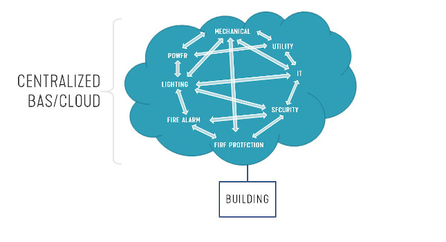
The phrase “internet of things” is often thrown around as a buzzword, but it has revolutionized how technology functions on a day-to-day basis. One basic concept of IoT is cloud-based computation and analysis. In a cloud-based building network, information is sent from sensors/actuators through building controllers and the building automation system to the cloud to be analyzed (Figure 1).
A BAS is a centralized control network that connects many controllers, sensors and actuators throughout a building. The term “cloud” refers to shifting computation from a local server to a remote server. A remote server will have more computational power than a typical local network/computer, which will allow for faster and more effective analysis of building data.