Industrial control system (ICS) replacements are inevitable as platforms age, vendor support ends and operational needs change.
Learning objectives
- Identify the core design questions to answer before the ICS replacement begins.
- Understand the key deliverables that reduce execution risk in operating facilities.
- Recognize how operational constraints drive phasing, cutover planning and testing.
ICS insights
- ICS replacements are high-consequence projects, and successful ICS modernization depends on a disciplined, four-stage approach that helps designers establish the baseline, defines required system behavior and risks, plans the migration strategy and sets clear execution and acceptance criteria without disrupting operations.
- Well-designed ICS replacements do more than refresh technology; they improve reliability, security, maintainability and long-term operational resilience.
- When the ICS replacements occur in operating facilities, the primary challenge is managing risk while maintaining continuity of operations. This article outlines a staged design framework that establishes a system baseline, defines system behavior and risks, plans a phased replacement strategy and specifies execution and acceptance requirements.
At-scale industrial control system (ICS) replacements are high-consequence projects because the control system is intertwined with the manufacturing facility operation, production, safety and compliance. Success depends on a disciplined design that captures what exists, defines what must not fail and plans how to migrate without disrupting operations.
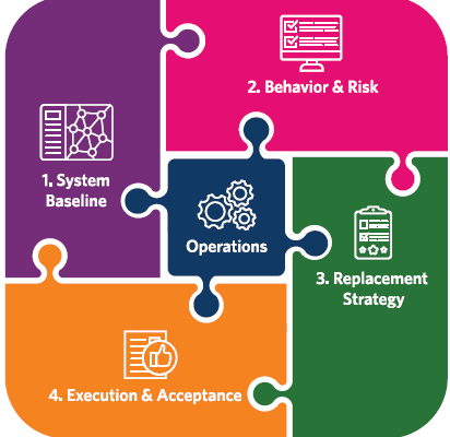
A practical approach organizes the work into four stages (see Figure 1):
- Establish the system baseline: Understand the existing systems that are in place and identify what elements must be reused or protected.
- Define system behavior and operational risks: Describe how the system functions and why.
- Plan the replacement: Determine the approach for how the target system will be built and how the existing system functionality will be migrated.
- Define execution and acceptance: Determine how cutovers will occur and how success will be verified.
The design stages should be executed in close coordination with operations to ensure that unplanned interruptions are minimized while the replacement approach incorporates improvements that optimize operational efficiency.
Stage 1: Establish the ICS baseline
Before making any modifications to an existing ICS, the system baseline should be documented. This baseline serves as the pre-replacement snapshot of the current ICS and all associated interfaces. Establishing this reference point enables informed decisions about component reuse, required replacements and the sequence of activities necessary to sustain uninterrupted facility operations.
In addition to as-installed diagrams, the baseline should include captured software and firmware versions, vendor support status and configuration backups for critical components such as controllers, network devices, servers and software. The identification of these items helps to both accelerate troubleshooting during migration and provide a reliable recovery path if an interim step introduces instability.
Network and architecture baseline
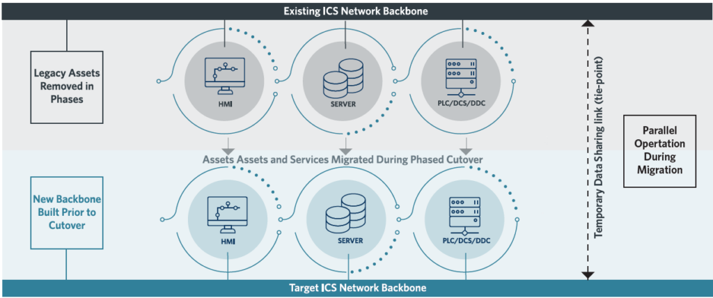
Before designing the replacement strategy for the ICS, it is imperative to develop and demonstrate an understanding of the existing system network architecture. Start by documenting the current network architecture and identifying interim requirements for parallel operation. In most replacements, the existing and target systems must operate simultaneously for a transition period, with a controlled tie-point for interim data sharing (see Figure 2). The baseline should include:
- Current network topology and identification of critical paths.
- Existing servers, workstations and data acquisition components that must remain functional during migration.
- Physical constraints (space, access, cable routes and raceway capacity).
- A high-level target network architecture that can operate independently while migration is in progress.
Using the existing network architecture documentation as a roadmap, complete a detailed inventory of all control system assets. This should include controllers, panels, network devices, servers, workstations, radios, firewalls, routers and any specialized interfaces. The objective is to determine which components must be replaced due to obsolescence or incompatibility, which assets can be temporarily retained and which interfaces will require special handling during cutover.
Develop input/output (I/O) lists for each controller or remote I/O location, including point type and termination information wherever possible such as terminal strip, terminal numbers, wire labels and conduit identifiers (see Figure 3).
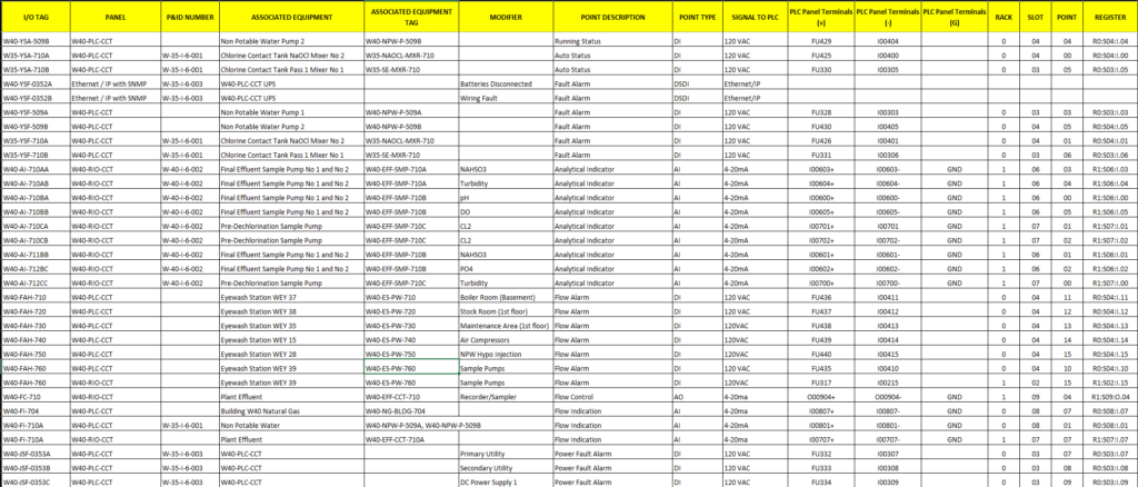
For communicated I/O and smart field devices, documenting network addresses, protocols and any vendor-specific configuration tools required for replacement or troubleshooting is necessary. Treat device communication settings as part of the I/O baseline so they are not part of rediscovery during commissioning.
Accurate I/O documentation directly reduces cutover duration and commissioning risk. When discrepancies arise between software databases and as-built drawings, flag them for field verification during design prevent contractors from encountering unexpected issues during cutover windows.
Stage 2: Define system behavior and operational risks
Understanding how the existing system operates is critical to achieving a successful ICS replacement due to the target platform typically requiring new application code, updated human machine interface (HMI) configuration and revalidated alarm and setpoint behavior. The goal of this stage is to document how the system must behave and to identify risks that could disrupt operations during migration.
Develop or validate control descriptions — whether in narrative form or as cause-and-effect matrices — for all areas in the replacement scope. When documentation is incomplete for the existing system, reconstruct operational intent through code review (see Figure 4), historical trend and alarm analysis and focused workshops with operations and maintenance staff.
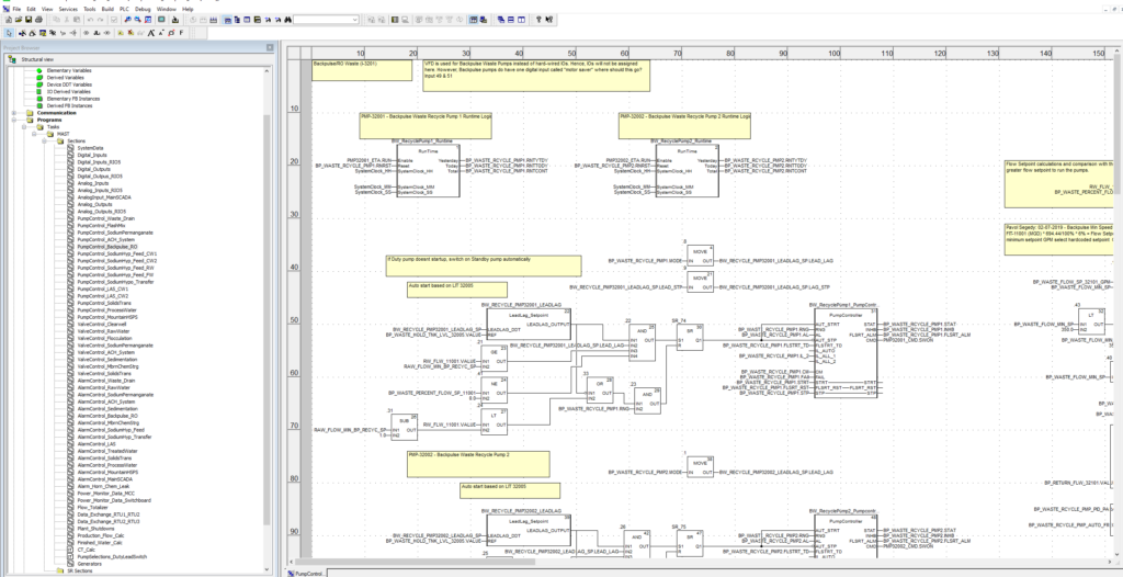
Validate these control descriptions against piping and instrumentation diagrams (P&ID), I/O lists and the existing HMI to ensure that each control loop has clearly defined inputs, outputs, permissives, interlocks, alarms and setpoints.
When the target system introduces new capabilities such as virtualization, improved alarming, better trend retention or standardized graphics, define which improvements are essential for Day One operation and which can be deferred until after the replacement is stabilized. This approach manages expectations, prevents scope creep and protects critical cutover windows. If the process warrants it, incorporate formal risk review methodologies into the requirements validation effort.
Data flow and cybersecurity requirements
Document how data currently moves in the existing system including control-to-control communications, control-to-historian data flows, historian-to-enterprise integrations, remote access pathways and reporting interfaces — and which of these flows is mandatory for compliance or operational continuity. Use this data-flow map to define the minimum required interfaces for parallel operation and for the post-migration system.
The target architecture should reduce inherited vulnerabilities through segmentation, controlled zones and conduits and least-privilege access principles. The series of standards included in ISA/IEC 62443 Series of Standards provides a widely recognized framework for defining security zones, conduits and technical requirements.
Stage 3: Plan the ICS replacement strategy
This stage combines the technical build plan with the operating reality of limited downtime. Rather than treating strategy, constraints and specifications as separate elements, approach them as a single integrated plan; constraints define the feasible strategy and the specifications translate those strategies into enforceable, actionable requirements.
Most at-scale control system replacements follow a predictable sequence:
- Build the target network backbone and computation environment including servers, virtualization platforms and domain or related services as applicable).
- Develop and test the target HMI and data services to ensure functionality, performance and compatibility before field deployment.
- Migrate controllers and I/O in logical increments such as by process area, train or unit operation to manage risk and minimize operational disruption.
- Retire legacy components only after verification testing and system stabilization, to confirm that the new equipment is fully functional.
Parallel-operation requirements should be explicitly designed, including the tie-points between networks and any temporary data interfaces needed to keep the facility operating during the migration of components and services from the existing to the target system.
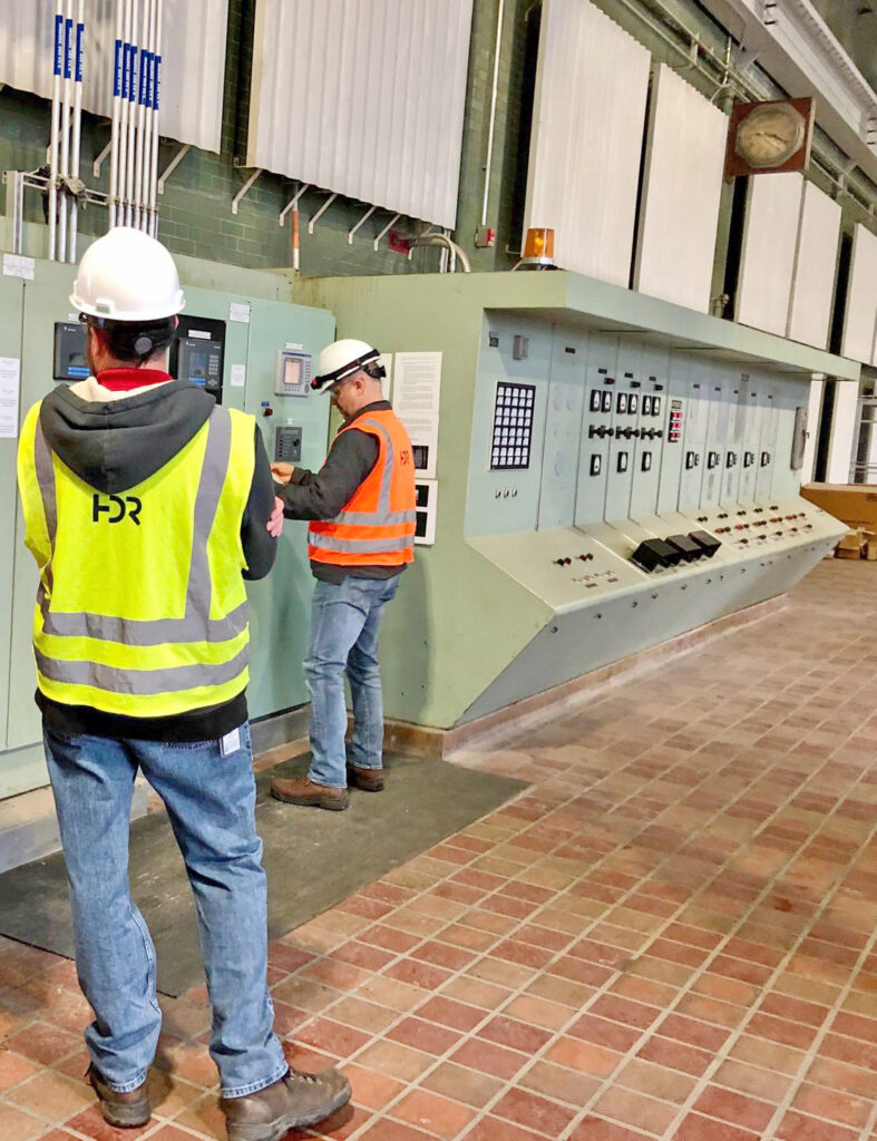
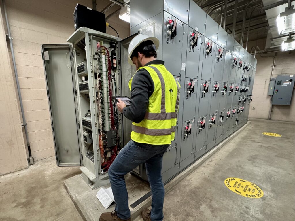
For each controller location, identify the preferred replacement method and the rationale for selecting it. This assessment will require time in the facility performing physical inspections (see Figure 5).
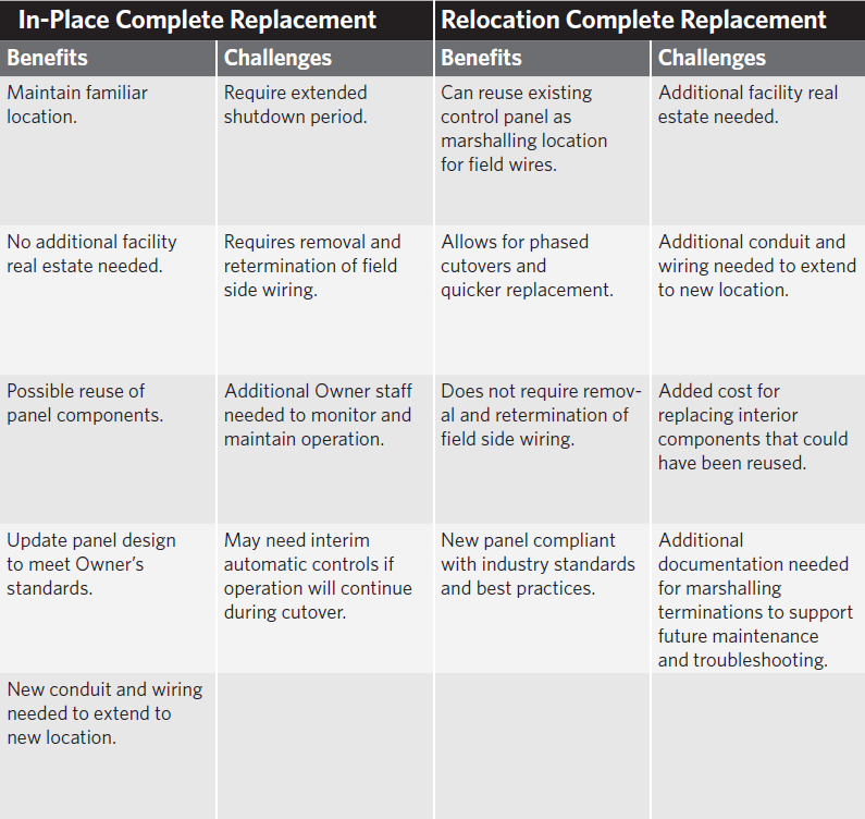
In practice, most locations fall into one of two replacement approaches:
- In-place replacement: Remove and install hardware in the existing location. This often requires carefully managed outage and extensive re-termination efforts.
- Relocation replacement: install new hardware or panels in an alternate location and migrate terminations through marshaling or a staged cutover. This can significantly reduce outage duration, though this often requires additional space and increases wiring complexity.
Figure 6 outlines the benefits and challenges associated with each replacement approach.
The design should select the approach that best aligns with operational constraints, physical realities and risk tolerance. For critical areas, explicitly identify interim control measures such as manual operation, temporary automatic control or train-by-train migration, and define the prerequisites that must be met before initiating cutover.
Operational constraints and specification requirements
Capture, in enforceable terms, the constraints that will govern execution:
- Allowed work hours, access limitations and safety/security requirements.
- Downtime windows and the maximum allowable duration for each outage, along with the operational consequences of any overrun.
- Seasonal or production constraints that influence scheduling,
- Prohibited means and methods such as restrictions on inline splicing or other practices that may compromise reliability or compliance.
- Contractor submittal requirements including detailed cutover plans, loop documentation, test procedures, rollback plans and staffing plans.
These requirements should be incorporated directly into the project specifications so the contractor is obligated to plan and execute within the facility’s operational boundaries.
Stage 4: Define ICS replacement execution and acceptance
This stage translates design intent into a repeatable cutover and verification process. Establishing clear prerequisites and acceptance criteria minimizes the risk of partial completion that leaves operations with gaps.
Define the sequence of cutovers by area or location and specify the minimum deliverables required before each cutover begins. Where possible, require a standardized format for cutover plans so each migration increment follows a consistent rhythm: readiness review, pre-cutover backups, field labeling verification, controlled cutover steps, defined roles and responsibilities for operations and the contractor and objective pass/fail criteria.
At a minimum require, require the following before initiating each cutover:
- Updated I/O lists and termination schedules.
- Complete loop documentation (loop sheets or equivalent).
- A detailed cutover plan outlining pre-cutover checks, step-by-step cutover actions, rollback steps and post-cutover verification.
- Operations sign-off on readiness and any interim operating procedures.
For each area, define how operations will be maintained during the cutover window — whether through manual operation, train-by-train sequencing or temporary automatic control — and specify the conditions required for each method to be acceptable. If a complete facility outage is permitted, maintaining operations during the cutover may not be required.
Testing, commissioning and stabilization
Specify a multistage validation process that verifies system functionality before, during and after installation:
- Progressive software demonstrations to verify control logic and HMI behavior before field work.
- Factory acceptance testing to validate panels, networking and application performance in a controlled environment.
- Site acceptance testing and commissioning to confirm wiring integrity, I/O functionality, network communications, redundancy and failover behavior, alarms and operator workflows.
Include clear and enforceable requirements for data validation — such as tag naming conventions, scaling, engineering units, alarm priorities and historical data collection rates — as well as operator usability expectations including screen navigation, alarm management workflow, standard trend templates. These “soft” requirements often determine whether a replacement project fails to meet operational expectations, even when the hard functions correctly.
Finally, require a stabilization period after each migration increment. This window allows operations to identify emerging issues and provide time for the contractor to tune the system before final acceptance. Structured stabilization prevents unresolved defects from compounding across multiple cutovers and supports a smoother transition to steady-state operation.
Successful ICS projects
ICS replacements in operating facilities succeed when thoughtful and deliberate design are used to reduce uncertainty. A staged approach that documents the baseline, verifies control intent and associated risks, integrates strategy with constraints and specifications and defines clear execution as well as acceptance criteria, enables phased modernization without jeopardizing operational continuity.
When done well, a replacement becomes more than just a technology refresh. It evolves into an opportunity to enhance reliability, strengthen security, improve maintainability and build long-term resilience.