Significant changes to the 2013 edition of NFPA 20: Standard for the Installation of Stationary Pumps for Fire Protection include a requirement for an alternate flow measurement means for flow meters, modifications to the water mist fire pump requirements, and limited service controller requirements.
Learning objectives:
- Understand the basic operating characteristics of fire pumps.
- Understand the basic types and operating characteristics of pressure regulating valves.
- Learn the most significant changes in NFPA 20-2013.
The 2013 edition of NFPA 20: Standard for the Installation of Stationary Pumps for Fire Protection has some significant changes intended to address known issues. A discussion of some issues that will likely be addressed in the 2016 edition of NFPA 20, including fuel storage and transducer reliability, is also included. Issues raised by a transducer recall occurred too late in the cycle to be resolved in the 2013 edition but will likely be addressed in the 2016 edition.
Following is a summary of some of the significant new requirements and the philosophy behind them. To help understand the changes, a discussion of fire pump discharge pressures and pressure regulating valves is included.
Dealing with pressure
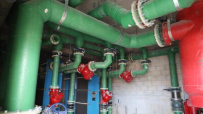
Fire pump discharge pressure: Centrifugal fire pumps increase water pressure by sending water through a spinning impeller. The amount of water that goes through the impeller is a function of water discharging through an opening downstream of the fire pump. The larger the opening, the higher the flow of water. If there are no openings, water will not flow through the fire pump but will “churn” within the fire pump. The pressure added to the water is inversely related to the flow rate through the fire pump, that is, the highest pressure occurs under “churn” (no flow) conditions.
NFPA 20 allows the “churn” pressure to exceed the rated pressure by up to 40%. The churn pressure typically exceeds the rated pressure by 10% to 20% for horizontal centrifugal fire pumps. NFPA requires a fire pump to deliver a minimum of 65% of the rated pressure at 150% of rated flow. Typically the suction pressure is inversely related to the flow rate: the water supply pressure decreases as the flow rate increases. The discharge pressure is the sum of the suction pressure plus the pressure added by the fire pump (see Figure 2).
Pressure regulating valves: Spring loading and pilot operation are the two basic operating mechanisms for pressure regulating valves. Early pressure regulating valves used a spring behind a seat. The valve operating pressure setting was based on the initial tension placed on the spring. In some valves the initial tension is field adjustable, while in others it is factory set. When the force from the water pressure exceeds the force applied by the spring, the seat opens until the forces equalize. Currently this type of operating mechanism is applied to small pressure relief valves, small valves in the sensing lines of pilot operated valves, and in pressure reducing hose stations.
Pilot operated valves apply system water pressure to the back side of a diaphragm to open and close the diaphragm. A small line with a control mechanism is connected between the back side of the diaphragm and the upstream piping to apply pressure to the back side of the diaphragm. A small pilot sensing line connected to the back side of the diaphragm is piped upstream, downstream, or both, depending on the application. This sensing line is used to increase or decrease the pressure on the back side of the diaphragm.
Pressure relief valves: Pressure relief valves are installed in a side outlet of the primary water path and regulate pressure by allowing a flow of water through the fire pump and pressure relief valve, thereby causing the fire pump to operate at a lower pressure on the fire pump curve. The flow through the pressure relief valve may be discharged to the atmosphere or returned to the fire pump suction. Older fire pump installations may use a large spring loaded pressure relief valve. These large spring loaded valves are difficult to adjust, prone to failure, and will exceed their set operating pressure by up to 25% before they fully open.
Newer fire pump installations primarily use pressure relief valves that are pilot operated with a sensing line from piping upstream of the valve, connected to the back side of the diaphragm. Under no-flow conditions, the side outlet path is normally closed by the diaphragm. If the upstream pressure is above the preset value, water is drained from the back side of the diaphragm, moving the diaphragm and increasing the size of the flow path through the pressure relief valve. Pressure relief valve issues are discussed in more detail later in this article.
Pressure reducing valves: Pressure reducing valves are installed in the primary water path and regulate the downstream pressure. Pressure reducing hose valves may use a spring mechanism for controlling downstream water pressure. The inlet and outlet pressures must be known to set the initial spring tension.
Pilot operated pressure reducing valves (also referred to as pressure control valves) have a sensing line connected downstream of the valve to the back side of the diaphragm. Under no-flow conditions, the primary water path is normally closed by the diaphragm. If the downstream pressure is above the preset pressure, water pressure is applied to the back side of the diaphragm, decreasing the size of the flow path through the pressure reducing valve.
Low suction throttling (pump suction control) valves: Low suction throttling valves are installed in the primary water path to prevent the suction pressure from falling below a preset pressure. These valves are pilot operated and have a sensing line connected from the fire pump suction to the back side of the diaphragm. Under normal conditions the primary water path is open. If the fire pump suction decreases to or below the preset value, water pressure is applied to the back side of the diaphragm, decreasing the size of the flow path through the valve.
Tank fill: Tank fill valves are installed in the primary water path to control the flow of water into a tank. These valves are pilot operated and can be controlled by a solenoid valve or a pressure sensing line connected from the tank to the back side of the diaphragm. Under normal conditions the primary water path is closed by the diaphragm. In a solenoid operated valve, opening a solenoid relieves pressure from the back side of the diaphragm, moving the diaphragm and causing the primary water path to open. If the tank fill valve is pressure operated, low pressure on the sensing line relieves pressure from the back side of the diaphragm, moving the diaphragm and causing the primary water path to open.
Multiple function valves: By using multiple sensing lines, a pilot operated valve can be trimmed to perform multiple functions. As an example, adding a sensing line connected upstream of the valve can allow a tank fill to prevent the upstream pressure from falling below a preset pressure.
The scope of NFPA 20 does not include pumps installed under NFPA 13D: Standard for the Installation of Sprinkler Systems in One- and Two-Family Dwellings and Manufactured Homes. NFPA 13D is limited to the design and installation of automatic sprinkler systems for protection against the fire hazards in one- and two-family dwellings and manufactured homes. Although the scope statement in NFPA 20 does not specifically exclude these pumps, NFPA 13D does not require listed pumps and references NFPA 20 only as a reference standard. One of the goals of NFPA 13D is to encourage installation of sprinkler systems in dwellings by limiting the cost. This issue becomes more complex when localities allow NFPA 13D to be applied to buildings that are not one- or two-family dwellings or manufactured homes. When applied to apartment buildings or other (typically residential) applications that must comply with NFPA 25, correlating components needed to perform the inspection, testing, and maintenance required by NFPA 25 may not be provided.
Controllers
The use of limited service controllers has been debated for multiple code cycles. They were initially introduced into NFPA 20 as a means to provide controllers for lower horsepower motors, and to provide a low-cost alternative to minimize the cost of retrofitting schools with sprinkler systems. Since their original introduction, many things have changed. Full-service controllers are now available for low horsepower motors, and the cost differential between full-service and limited service controllers has decreased significantly (the manufacturing cost differential was reported to be as low as $100). Another concern is the use of limited service controllers for applications which were not contemplated by NFPA 20. These non-contemplated applications include foam pumps in aircraft hangars and other applications where high value and/or high life safety risks are involved and the increased reliability of a full service controller is needed. Previous proposals to change the requirements on limited service controllers have varied from eliminating limited service controllers altogether to removing the 30 hp limitation. Also, no statistical analysis has been conducted to evaluate the reliability of limited service controllers.
There are two main issues with the thermal magnetic breaker that was allowed in limited service controllers prior to the 2013 edition of NFPA 20. The first concern is that the allowable trip time of 200 seconds allowed for a thermal magnetic breaker will cause burnout of a locked motor. When this occurs, the limited service controller may be reset by someone without realizing that the motor is non-operational. The second concern is the extended time it takes to reset a limited service controller because the thermal magnetic breaker must cool down before it will reset. In case of a fire, time delay can be critical. A limited survey in the Chicago area of pump motor replacements revealed that motors with 25 hp or less were replaced at a significantly higher frequency per installed base than higher horsepower motors.
The deadlock in limited service controllers was resolved by a “compromise” to change the breaker requirement on limited service controllers to match full-service controllers. This will likely further reduce the price differential.
Water mist pumps
Water mist technology is starting to be accepted to protect hazards that traditionally have been protected by sprinkler systems. For some of these applications, multiple water mist pumps are arranged in parallel to operate as a unit, with additional pumps turned on as additional nozzles operate. In some applications the small water mist pumps are mounted on the same frame and designed with variable speed operation capability. NFPA 20 has traditionally treated fire pumps as individual units and made requirements accordingly. Even in applications such as refineries and aircraft hangers, where multiple fire pumps must operate to supply the full demand, NFPA 20 requires an independent controller, pump test header, and pressure relief valve (if required) for each unit.
Water mist pumps are low-volume pumps that develop medium to high pressures. Because these pumps operate as a single unit, the NFPA 20 committee felt that it was appropriate to add requirements that better fit a “unit” concept. A definition of a “water mist positive displacement pumping unit” was added to allow water mist pumps operating in parallel to be treated as a unit. A significant change allows a single controller to be used for water mist pumps operating in parallel as a “water mist positive displacement pumping unit.” Another change allows a “water mist positive displacement pumping unit” to serve as a jockey pump. In order to assure that a “water mist positive displacement pumping unit” serving in a jockey pump mode generates a signal and switches to a fire pump mode when a nozzle operates, the jockey pump mode cannot provide more than half of the nozzle flow of the smallest system nozzle when the standby pressure is applied at the smallest nozzle.
Special treatment was required for pump curves. The manufacturer must provide both individual and unit fire pump curves with and without variable speed features deactivated.
Diesel fuel oil
An expert gave a presentation on the changes in diesel fuel oil to the NFPA 20 committee. As the industry moves toward biodiesel (especially in Europe), the long-term storage of diesel fuel required for diesel driven fire pumps requires more attention. Bio-based diesel fuel is more susceptible to "bugs” than petroleum-based diesel fuel and is not intended for long-term storage before consumption. Regular inspection and testing are required to make sure deterioration of the fuel will not adversely affect the diesel engine. A requirement for providing a listed active fuel maintenance system on fuel tanks was passed by the NFPA 20 committee but overturned at the NFPA technical session. This leaves the 2013 edition of NFPA 20 with minimal guidance for maintaining diesel fuel.
A significant reason for overturning the requirement for a listed active fuel maintenance system was to allow for other options. This is an international issue that likely will be addressed in the 2016 edition of NFPA 20.
Series fire pump operation
An ongoing debate has developed over allowing vertical staging of fire pumps that operate in series. The debate continued to the NFPA technical session, with the final result that vertical staging is still permitted. A detailed discussion of the issues involved with vertical staging of fire pumps is included in “Fire Pumps In High Rise Buildings” in the July 2009 edition of Consulting-Specifying Engineer.
The primary reason for vertical staging of fire pumps is perceived lower cost. In general, non-vertically staged fire pumps will require two express risers to the supply the higher zone that could be supplied through standpipe risers on vertically staged fire pumps. However, vertically staged fire pumps will require a pump test riser from the higher floor to an appropriate discharge location probably on the ground floor, and also requires running electrical power with a 2-hour fire rating requirement to the vertically staged fire pump. The actual cost difference may be minimal and should be evaluated on a case-by-case basis considering the cost impact of both piping and electrical supplies.
It is likely that this issue will be readdressed in the 2016 edition with the possible addition of remote operational capabilities to address emergency operation issues.
Pressure relief valve
Issues with pressure relief valves continue to surface, with one committee member reporting a significant number of events where a pressure relief valve that was piped back to the fire pump suction would apparently be completely open. This results in a significant impairment to the fire protection system that may go unnoticed until the water is needed for an actual fire. This issue can occur any time the discharge from a pressure relief valve cannot be observed. When a pressure relief valve is piped back to a suction tank, a means to observe the discharge should be provided (see the sight glass in Figure 3, item 2).
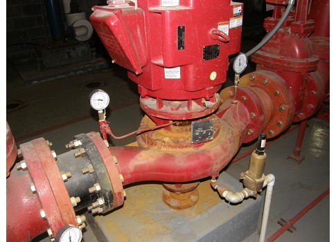
A fire pump adds energy to the water passing through it. When no water is discharging, the energy will be in the form of heat added to the water. To prevent water overheating at churn, a circulation relief valve located between the fire pump and fire pump discharge check valve is required to operate at churn pressures, but should not operate when the fire pump is flowing water (see circulation relief valve in Figure 4). When water is flowing through a pressure relief valve or a test loop piped back to suction, the pressure will be lower than churn pressure and the circulation relief valve designed to operate at churn will not operate. However, when circulating water though a closed loop, a fire pump adds even more energy to the water passing through it than under churn conditions. An additional circulation relief valve is required when a relief valve is piped back to the pump suction. This additional circulation relief valve should be set to operate below the 150% pump discharge pressure.
Without proper operation of the circulation relief valves, the temperature of the water will rise. In addition, if the pressure relief valve is wide open, it may cause a diesel engine (if used) to exceed its rated horsepower. When the higher temperature water is sent to the heat exchanger for cooling, the engine may overheat. In one case I am aware of, a diesel engine was destroyed and this scenario appears to be the cause.
An argument was presented that if the pressure relief valve discharged to the atmosphere, the extreme flow of water would not be ignored. Currently pressure relief valves are permitted and required only to prevent overpressurization for two reasons:
- Diesel overspeed conditions
- Failure of the variable speed mode on variable speed pumps.
Under normal operating conditions the pressure relief valve should not operate even under churn conditions. However, older fire pump installations may use the pressure relief valve to “trim” the fire pump discharge and the pressure relief valve may discharge a large volume of water well beyond churn conditions. The committee felt that the pump installations in the reported incidences did not conform to current requirements and returning pressure relief valve pipe to the pump suction was appropriate for the limited use of pressure relief valves permitted by NFPA 20.
While piping a pressure relief valve or test loop back to suction is still permitted, a requirement was added for heat exchanger cooled diesel engines to monitor the temperature of the cooling water and shut 4down the engine while operating in the test mode (only) whenever the water temperature at the engine inlet of the heat exchanger exceeds 104 F.
As noted earlier, a separate circulation relief valve is required by NPFA 20 whenever the pressure relief valve is piped back to suction. The additional circulation relief valve is critical to prevent the fire pump from overheating. Tier 3 environmental requirements that limit the intake air temperature cannot be maintained without limiting the cooling water temperature. A circulation relief valve on a pressure relief valve piped back to suction is shown in Figure 3, item 9.
Pump circulation relief valves
For pipes in areas subject to seismic activity, the clearance around the pipe passing through walls, floors, or ceilings must meet the seismic requirements referenced in NFPA 13.
Torsional vibration analysis is always needed for diesel-engine driven vertical turbine pumps. Harmonics that can develop at specific rpm can cause the driver to self-destruct if not accounted for. Requirements to clarify the torsional vibration analysis were included in the 2103 edition of NFPA 20.
The committee’s experience is that flow meters are highly inaccurate, and a requirement for an alternate means to measure the flow after it has passed through the flow meter has been added to NFPA 20. The alternate measurement allows verification of the accuracy of the flow meter. In most cases this will require a pump test header downstream of the flow meter. Figures showing the correct location of a pump test header were modified in NFPA 20. While many flow meters cannot be adjusted, correction factors may be established. Where the accuracy of the flow meter cannot be established, it should be replaced.
The U.S. Consumer Product Safety Commission recall of approximately 25,000 Gems model 3100 pressure transducers affected approximately 15,000 fire pumps. The issue was not picked up in time for action in the 2013 edition of NFPA 20 but will likely be reviewed in the 2016 edition. While the recall was limited to one model of one manufacturer, it does point out a potential issue that could be monitored in a fire pump controller.
Mercoid switches (no longer used in modern controllers), the primary pressure actuation method prior to pressure transducers, also are subject to failure. However, the interaction between a controller and a mercoid switch is limited to open or closed contacts, which does not allow the controller to detect any issues with the mercoid. Transducers are interactive, providing a continuous voltage reading to the controller. It is possible for the controller to monitor these voltage readings for abnormalities. This capability that was not available for mercoid switches will form the basis for the discussion for the 2016 edition of NFPA 20.
Consideration was given to processing a tentative interim amendment (TIA) to address this issue. However, the NFPA 20 committee believed the current issue was being addressed through the recall mechanism and any modifications to NFPA 20 would not meet the emergency nature needed to issue a TIA because it would only affect future controllers without improving the current situation.
Low-suction pressure throttling valve
Any device that restricts the flow of water is discouraged in a fire pump installation. Some jurisdictions have requirements to limit the pump suction pressure to a minimum pressure (typically 20 psi) through the use of a low-suction throttling valve (also referred to as a pump suction control valve). These valves are installed downstream of the fire pump but monitor pressure upstream of the fire pump, and will partially close as necessary to maintain a preset minimum suction pressure.
Because these valves limit the minimum suction pressure, the design must maintain the suction pressure at the required flow rate (the higher of 100% rated flow or system demand) above the preset minimum.
There is a significant pressure loss through these valves that must be accounted for in determining the available flow and pressure downstream of the valve. A low-suction throttling valve should be wide open as long as the pressure remains above the minimum suction pressure, and the friction loss can be calculated using the Cv value of the valve in the formula:
P = (Q/Cv)2
Where:
- P = pressure loss across the valve
- Q = Flow through the valve in gpm
- Cv = Friction loss factor as determined by the manufacturer in gpm/psi0.5
Pressure-reducing valves
NFPA 20 does not permit the installation of pressure-reducing valves (also referred to as pressure-control valves) within the fire pump suction or discharge piping. Piping before the suction or after the discharge control valve is not within the jurisdiction of NFPA 20. The suction components consist of all pipe, valves, and fittings from the pump suction flange to the connection to the public or private water service main, storage tank, or reservoir that feeds water to the pump. The discharge components consist of pipe, valves, and fittings extending from the pump discharge flange to the system side of the discharge valve.
NFPA 14: Standard for the Installation of Standpipe and Hose Systems does permit the use of pressure control valves to control the pressure on vertically zoned standpipe systems. However, meeting the NFPA 14 requirement that the failure of a single pressure control valve does not overpressurize more than two hose valves requires a series arrangement of pressure control valves that must accommodate both low and high flow rates. A full flow test method also must be provided for the valves. NFPA 20 does not prohibit using the pump test header to test these valves.. This is a complex arrangement, and the use of pressure reducing valves should be thoroughly understood before using this design approach.
Figure 5 shows a testing arrangement for a single pressure reducing valve installed downstream of the fire pump discharge control valve.
Gayle Pennel is a project manager with Aon Fire Protection Engineering. His expertise lies in fire protection systems and water supplies. He is currently chairman of the NFPA 20 committee and serves on the NFPA 25 committee. He has designed fire protection systems for super high-rise and large exhibition centers, as well as industrial sites. Pennel has consulted on pressure surge, corrosion, and other fire protection failure issues and has successfully presented fire protection design alternatives to state and local authorities.