How does an electrical engineer decide between fuses and circuit breakers? The answer: It depends
It is useful for both electrical and nonelectrical engineers to understand basic features when selecting, specifying and applying electrical distribution systems. To narrow the broad scope of electrical distribution, this discussion will focus on practical considerations for specifying electrical distribution systems, with a focus on fuses and circuit breakers.
Learning Objectives
- Understand basic features when selecting and specifying electrical distribution equipment.
- Know the types of overcurrent protection devices, such as circuit breakers and fuses, and switchgear as it is outlined in UL 1558.
We are starting out with an excerpt directly from Article 90, the introduction to NFPA 70: National Electrical Code. The stated purpose of the code is to safeguard people and property from the hazards associated with the use of electricity. So when we design electrical distribution systems, the typical focus is on ensuring that the equipment and wiring methods that we specify have appropriate capacity and configuration to reliably store whatever loads may be connected at that system.
However, what we often lose sight of is the fact that there are inherent hazards associated with the use of electricity. Ultimately, when we design electrical distribution systems, we need to be able to interrupt the unintentional flow of electrical current before it can cause harm to people or damage equipment. Let’s start with the base — how do you characterize what that unintentional current is?
When we talk about unintentional or objectional electrical current, we’re typically talking about overloads and faults. These two are distinctly different things. Let’s first take a look at what the concept of an overload is. Based on the NEC definition of fault, such as a short circuit or a ground fault, isn’t an overload. If you read into this, the key takeaway should be that the current is flowing through the circuit that you designed through that normally expected path, whether it be through a transformer, a motor, a feed or whatever load or wiring method, you may have connected to that circuit.
However, the magnitude that that current is more than what you want. It could be sustained, locked order current, so to say, with a seize motor, too many appliances plugged into a circuit, it could be any number of things. Faults or short circuits on the other hand are where current flows through a path other than the intended load or circuit. Oddly enough, the NEC doesn’t formally define all types of general faults or short circuits. Only ground faults are defined within Article 100.
The ground fault definition, also in NEC, is interesting. We have two different types of conditions, overloads and faults. How do you safely interrupt this abnormal flow of electricity? With an overcurrent protection device. But let’s continue with another excerpt from the Article 100 definitions, the definition for an overcurrent protection device, that’s on this slide.
What qualifies as an overcurrent protection device? This could be a fuse, it could be a mobile case circuit breaker, it could be a protective relay. However, what isn’t noted here very conspicuously, is the timing requirement — how quickly that device needs to operate. While the code in some cases makes mention how quickly a device needs to operate under very specific conditions, it generally is more a function of the UL standard associated with that particular device type.

Fuses
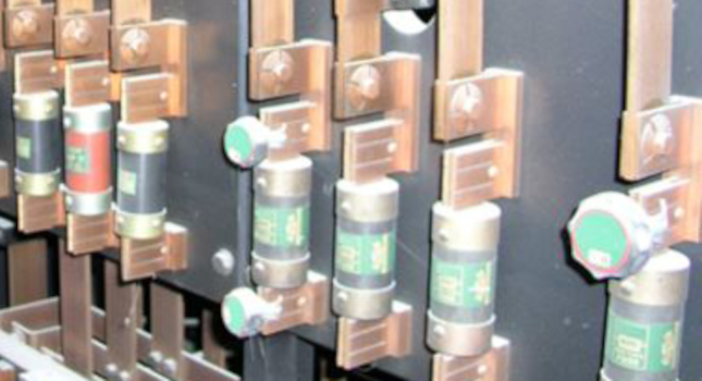
Let’s start with fuses. Fuses have been around for an extremely long time. Figure 1 shows part of a 5,000 amp, live front switchboard from the 1940s. You can clearly identify the individual fuse clips that they’re seated in everything else. Although it seems wildly obsolete and unsafe, this switchboard is actually still in operation. even though fuses have been around for what seems like forever, there’s no formal definition within the NEC for what a fuse is.
As such, we have to rely on definitions from another source. There are two applicable standards for fuses, UL 248 and NEMA FU1. Let’s start with the NEMA definition. A fuse is a protective circuit that opens a circuit during a specified overcurrent condition by means of a current responsive element. That element is the fusable portion of the fuse that melts during an overcurrent condition to clear the circuit. Basically, that’s a sacrificial conductor that melts, maybe even vaporizes, depending on the magnitude of your current.
When exposed to an overcurrent condition, it opens the circuit and prevents damage to those downstream devices. Let’s take a closer look at how a fuse works. Under normal operating conditions that element has reasonably low resistance, so it is functionally no different from any other conductor.
However, in an abnormal operating condition, we depend on a sacrificial element. We either have to melt or vaporize an element to open and interrupt a circuit. If that happens in free air, the act of melting an element and releasing that energy that in of itself could be potentially dangerous.
As such we have to somehow contain or dissipate that energy. That element is installed within that cartridge body and it’s usually surrounded by sand to contain and dissipate that released energy to quench any arc that’s formed. Traditional single element fuses are a compromise. Either protecting against short circuit or protecting against an overload condition. You can design that single element to melt very quickly and have it be very fast-acting or you can sacrifice the speed and have it be a time-delay type fuse.
But this is a pretty significant trade-off and is unacceptable when you’re trying to protect loads of very high inrush currents like motors and transformers. To address this issue, the fuse industry came up with the concept of a dual element fuse. Now that’s exactly what it sounds like. You have two separate elements connected in series together, one optimized for the low-magnitude overcurrent condition and the other for the high-magnitude fault condition. The vast majority of fuses that you encounter in low-voltage power distribution systems will be of this dual-element type.
Let’s move on to how the element and the fuse reacts to various magnitudes of overcurrent. Based on what we’ve seen so far, you should be getting the impression that these overcurrent protection devices will react very differently, depending on how much current they see. Whether it’s a minor overload or a bolted fault on the other side of the spectrum. To be able to compare two different types of overcurrent protection devices is something that’s called a time current curve.

All manufacturers have these and are of similar formats, so you can make easier comparisons between two different devices. If you look closely at Figure 2, you notice that the scales aren’t linear, this is a log-log graph. Our per unit values go from 0.1 to 1, to 10 to 100 and so forth and so on. And these time current curves time and seconds is always on the vertical Y axis and current and amps is on the horizontal X axis. And this particular time current curve, this for our generic 100-amp fuse.
The red band that you see here represents the minimum and maximum melt times for the elements in that fuse. Everything to the left of that curve is normal operating conditions and the fuse will not open. Once you hit the red band or go to the right of it, the fuse will open the circuit. You can see that thin red band, it has some weight to it. This is due to manufacturing tolerances. The fuse is guaranteed to open somewhere within that band, not necessarily an exact number, but somewhere in that band.
You can also see if you follow the graph up to time scale toward the top at the 202nd mark, if you cross reference that with current, you can see that the fuse actually holds substantially more current in a hundred amps for that period of time. Before we leave the sign, let’s take a look at the bottom of this curve. And you can see where we have a very high magnitude of current, how that fuse reacts in a fault condition. This will become more important when we’re comparing these as circuit breakers.
Circuit breakers
Let’s move on to circuit breakers now. Again, the NEC provides the definition. Based on this definition, a circuit breaker can be open and closed against all magnitudes of current, up to its short circuit rating, basically acting as a switching device. The UL standard applies to most common types of circuit breakers, molded case circuit breaker, UL 489. Again, the NEC doesn’t necessarily dictate how quickly a device must interrupt that abnormal flow of current. That requirement is defined by that UL standard.
One important point is that when UL test circuit breakers are tested for the rated ampacity and free air. When they’re installed within an enclosure, unless they are specifically rated for 100% duty, they must be derated to 80% when subjected to continuous current. Continuous currents are defined in the NEC for any load that is sustained for three hours or greater.
We have two distinct conditions that we’re trying to protect against, overloads and faults.
These two conditions are characterized by the magnitude of unintentional current. There’s a big difference between these two. We saw how a dual element fuse addresses these two conditions. But the question is, how does a circuit breaker address those same two conditions? A breaker does this by two distinct mechanisms, a thermal function and a magnetic function. The thermal function is accomplished with a bimetal strip. The bimetal strip is two interconnected pieces of metal and these two pieces of metal have slightly different coefficients of thermal expansion.
They will shrink and expand at different rates when heated like resistive heating when you have current flowing through them. This causes to strip to bend and release a latch to trip the circuit breaker open. The magnetic portion of the breaker works on a principle of electromagnetic fields created by the flow of current. The magnitude of the field is proportionate to the magnitude of current. Through designing the breaker, you can create a magnetic field that will force us switching our mature open.
More current means greater magnetic field, which will open the context much faster. When subjected to full fault current, the typical circuit breaker will open in a ½ to 1 cycle. When we look at time current curves a bit later, this will become a little bit more apparent. In this case, we have the bimetal element that handles also overload side of it. We have a magnetic element that handles that short circuit part of the equation.
And when you think about it, it’s almost like a mousetrap. Once you trip that latch, the spring will draw the circuit breaker open. And either the magnetic element or the bimetal element can trip that latch.

Let’s move on to how a thermal magnetic circuit breaker responds to various magnitudes of overcurrent. Figure 3 shows a time current curve for a generic molded case circuit breaker.
Again, we have a log-log graph of this device response of various level of current. The blue band that you see represents a minimum and maximum trip throughout the controls for this breaker. Everything to the left of the curve is normal operating conditions and the breaker will not open. And again, sum the fuse with everything on the right side of it will open and interrupt the circuit. However, you can see that blue band is much wider than the fuse we were looking at before.
The breaker is guaranteed open somewhere within that band, but there’s a lot more uncertainty regarding exactly where. Finally, at the base of the time current curve, we see that instead of a smooth curve at the bottom, we have a weird dog leg at extremely high current. Basically, a level current that you would typically expect with something like a bolt vault. You can see that response extremely fast, again, ½ to 1 full cycle, but that blue area extends out to the right. Now, we have a certain level of uncertainty.
All UL 489 breakers have this characteristic dog-leg in the instantaneous region, which can become a selective coordination issue. With some types of south state trip units for a circuit breakers, you can adjust the pickup setting, but if the breakers are listed under UL 489, it cannot be defeated, only adjusted. Again, the equipment downstream of this that you’re trying to protect with these breakers is simply only rated for three full cycles of all current.
Now, if a fixed mechanism like that for a generic fuse of circuit breaker, we have pretty well-defined characteristics regarding how each device will respond to magnitudes of overcurrent. But in an electrical distribution system, we have multiple devices in series, each with its own characteristic time current curve. When we design electrical distribution systems, we’re trying to isolate an abnormal condition to the smallest portion to the distribution system. We want the device closest to the fault to overload to operate first, to have what we call selective coordination.
With multiple devices in series, we found to be some overlap. And we’ll lend some uncertainty regarding what device will trip first. Given the various types of scenarios that you may encounter, being able to tweak or make minor adjustment on how that individual breaker reacts to certain conditions, can make all the difference in the world. To this end, some breakers can be provided with an electronic trip unit. With electronic trip units, we’re replacing a purely mechanical tripping mechanism like in that picture, with an intelligent module that send us the true root mean square current flowing through it with current transformers.
Depending on the breaker, you can shape or tweak multiple portions at a time current curve. These trip units sense overcurrent conditions very quickly, but you’re limited by the fact that it still has to operate a mechanism to open a circuit. See we’re little short on time.

Fuses versus circuit breakers
We talked about both fuses and circuit breakers. Let’s directly compare the operate and characteristics into the two. Of course, there’s a credible variety of fuses and circuit breakers each with its own specific time current curves. However, to illustrate a point, Figure 4 shows generic fuse and circuit breaker time current curves.
This picture is a direct overlay of both of these. The fuse is red, the circuit breaker is blue. When they are overlayed, the difference is quite pronounced. You can see that the characteristic transition between the magnetic function and the thermal function and the blue band is at about half a second or 30 cycles. We can also see that in this particular case, the circuit breaker reacts considerably faster in the overload region of the graph at the top.
However, when we take a look further down in the short time region of the graph where the magnetic function of the breaker operates, there’s pretty far high uncertainty regarding where the circuit breaker will clear the fault in comparison to a fuse.
If we go down to the bottom of the graph again, that dog-leg is characteristic of a thermal magnetic breaker. That top of that dog leg is at one cycle, 0.0167 seconds. The circuit breaker can trip anywhere within that shade of blue region. Whereas with the red band representing the average melt time for the fuse is really well defined in this region. We don’t know if the fuse or circuit breaker is going to catch first.
However, we’re not here to say that fuses or circuit breakers are better or worse, rather based on your particularly application, you should understand relative advantages and disadvantages of each and then make a determination what makes the most sense for your budget protection.
Most fuses are current limiting, but there is a concept called threshold current ratio. Basically, if the fault current is equal or greater than the threshold current, the fuse is current limiting and this ratio can be anywhere from 30 to 65 times rated and passive fuse. This is great when you have a high level of available fault current, but for low magnitudes of fault current, like an arc fault event, they may not be particularly effective at limiting their fault current.
We also have pros and cons for circuit breakers. One of the primary advantages that we have is we can have solid state trip units that we can perform additional functions that the fuse can, we can shape the shape of our time current curve so it reacts differently.