The John W. Olver Transit Center zero-net energy (ZNE) project is a high-performance building designed with reduced energy loads, passive design strategies, maximized efficiency of mechanical and electrical systems, and on-site power generation.
Learning objectives
- Understand net zero energy buildings (NZEBs), and how they are defined.
- Learn the codes, standards, and guidelines that offer engineers a path toward zero-net energy (ZNE) design.
- Via a case study, see an example on how to design a ZNE facility.
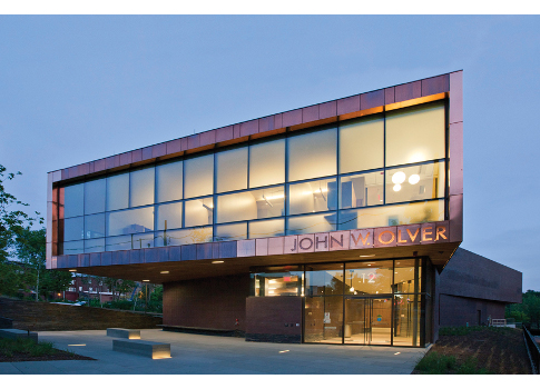
Located in the heart of Greenfield, Mass., the 3-year-old John W. Olver Transit Center (OTC)—an intermodal depot for all of the area’s fixed-route bus lines and private intercity, taxi, and paratransit (community transport) services—is an example of a successful zero-net energy (ZNE) project. It is the first ZNE building of its type in the United States.
At a project cost of a little less than $11 million (including the site), the two-story, 24,000-sq-ft building houses the offices of the Franklin Regional Transit Authority (the public transportation provider for this part of Massachusetts and client for the OTC) and the Franklin Regional Council of Governments. The building comprises offices, community space, a waiting area, a café, storage, and restrooms.
Project goals were developed by both the client and design team in the early stages of planning, and were identified to achieve a ZNE building; use energy-efficient, user-friendly systems; be sustainable in operation; and optimize capital and running costs.
With objectives and goals outlined at the outset, the iterative process of aiming for high-performance was fully incorporated into the design. This strategy involved reducing loads, employing passive design strategies, maximizing efficiency of mechanical and electrical systems, and generating power on-site from renewable sources. When designing a ZNE building, one of the first design decisions to make is its orientation, which can impact heating, lighting, and cooling costs. The building orientation was fixed by the requirements for the bus driveway and parking.
Because the orientation was fixed, the Arup team worked closely with Charles Rose Architects (CRA) to optimize the location of spaces within the building to create buffer spaces where possible. Elements such as storage, plant rooms, and bathrooms were located on the west side of the building, which insulated the offices on the east from the low angle solar gain. In addition, the façade insulation levels were increased beyond what is required by the Massachusetts Code with an R-42 roof and R-33 to R-36 walls. Where reasonably possible, wider temperature and humidity comfort bands were agreed upon with the client for the design of the HVAC and lighting systems.
Creating goals
As with any high-performance building, developing goals early—specifically those concerning ZNE—is critical to success:
- Begin the energy-modeling process at schematic design and continue to refine it through construction documents. Additionally, checking performance as equipment is selected by the contractor is recommended.
- Agree input assumptions to the model with the users such as occupancy schedules and client-purchased equipment, i.e., computers, servers, and process loads such as kitchen equipment. Reinforce this through the design and issue it for feedback at each phase.
- Ensure that the building is fully commissioned, and have a strategy for ongoing measurement and verification so that performance enhancements persist. Also educate both facilities staff and end-users so that they can contribute to the building’s success.
- Celebrate achieving ZNE. Providing feedback on strategies used and performance achieved will help future designers achieve similar goals.
Passive strategies
The daylighting strategy for the OTC ground floor was fairly straightforward. Because the space primarily consists of a waiting area with transient users, the light level targets were lower than in the offices. The glazed eastern and southern façades provide most of the light for this waiting area. The larger plan of the building’s second floor creates an overhang above this glazing, reducing direct sunlight penetration and glare, aiding lighting levels and visual comfort, and reducing thermal loads on the façade glazing.
The second floor comprises office space on the north, east, and south sides, and program requirements dictated that private offices occupy the areas near the façades.
To assess the quantity of daylight throughout the second floor, an initial “daylight factor” study was completed. This is a measure of the amount of daylight at a point inside as compared with an unobstructed point outside; office daylight factor targets are typically 2% to 5%.
The south and east glazing for the second-floor offices is partially covered by perforated copper screen. This both reduces glare in the office space and the direct solar load. To reduce electric lighting in the open office space located in the center of the floor plan, daylight is provided through a combination of clerestory glazing. Skylights were added so that the entire space is illuminated.
To further understand the daylight performance and provide accurate input to the energy modeling, an annual illuminance simulation was performed for each hour of the day. Through the use of these various analysis tools, the potentially competing elements of shading and available daylight could be assessed.
This analysis determined the “daylight autonomy” for each workstation in the office space—the percentage of operating hours during a typical year when illuminance levels from daylight can be expected to exceed the light level design criteria, allowing electric lighting to be turned off. Daylight autonomy is expressed as a percentage.
The project team defined 75% daylight autonomy as an appropriate target; for 75% of all operating hours there would be enough daylight for electric lighting not to be required. It was calculated that 89% of the workstations on the second floor met this criterion, and 100% achieved a daylight autonomy of >50%.
The west-facing lobby glazing is screened by an extension of the brick cladding, which has selected bricks removed to form an external egg-crate-type shading device. Only the north-facing offices are fully glazed, providing indirect daylight and long views back to historic Greenfield.
Energy-efficient systems
A number of strategies were employed to enhance the efficiency of the building systems.
Chilled beams—Because fan energy is one of the largest building energy uses, an active chilled beam system was chosen for the office areas. This combines water-based “sensible cooling” at the room level with “latent cooling” via the air-handling unit (AHU) system, resulting in less conditioned air having to be moved through the building. In addition, smaller AHU equipment and ductwork have a secondary benefit of reducing the building footprint and envelope.
Ground-source heat pumps—Primary cooling and supplementary heating are provided through ground-source heat pumps, which use the earth as a heat sink in summer and as a heat source in winter for chilled and hot water. The OTC has 22 closed-loop geothermal wells, each more than 400-ft deep. During the summer, the heat pumps provide chilled water to both the AHU and the chilled beams. In winter, the heat pumps are bypassed and the glycol-dosed water is pumped through a fresh-air preheating coil in the AHU and to balance the summer heat-rejection load.
Transpired solar collector—Almost all of the south-facing opaque façade at the second floor forms a transpired solar collector. This strategy is used to preheat ventilation air in the winter. The AHU draws the incoming fresh air through perforations in the collector plenum. The collector has a dark exterior color, which absorbs the winter solar radiation and preheats the air. In addition to the winter energy savings, the added cladding to the south façade reduces the summer cooling demand by shading direct sunlight. In the summer, the transpired collector is bypassed so as not to overheat the incoming air.
Lighting—The OTC’s lighting systems were designed to minimize the energy used for artificial lighting by extensive use of energy-efficient LED sources. Lower overall light levels are used in open and private offices to reduce the installed lighting power, but local user-controlled task lighting is provided for as-required individual needs. The careful application of new lighting technologies and aggressive lighting power densities resulted in a 44% reduction of installed lighting power as compared with a Massachusetts code-compliant building, which at the time referenced ASHRAE Standard 90.1-2007.
Advanced lighting controls—To help meet the project energy goals, a comprehensive building lighting control system connects to occupancy sensors that automatically shut off the fixtures when the space is empty, and photo sensors that provide continuous dimming when sufficient daylight is detected.
The lighting control system ensures that all spaces are adequately lit when occupied, and do not consume energy when unoccupied. In addition, the system zoning, control, and set points can be easily reprogrammed from a tablet or smartphone to cater to changing user requirements and allow for ongoing performance optimization. All regularly unoccupied spaces, such as plant rooms and storage closets, have occupancy sensors to ensure lighting in these areas is not left on when not in use.
Energy recovery—The central AHU includes multiple energy-recovery technologies (air-and water-side heat recovery). An enthalpy wheel transfers energy between the supply and exhaust air streams, recovering both sensible and latent energy that would otherwise be wasted in the exhaust air.
A refrigerant-based wraparound heat pipe heat-recovery exchanger is included at the chilled-water cooling coil to recover heat. For the active chilled beam system, humidity control is provided by overcooling the air to condense out the excess moisture, which then requires reheat to achieve the desired supply air temperature. This was accomplished using heat pipes that transfer heat from one air stream to another via a medium that alternately changes from a vapor to a liquid, absorbing and releasing energy. The heat pipes wrapped around the cooling coil precool the supply air before it hits the coil, allowing it to condense out moisture more effectively. The heat pipe then reheats the air on the rear of the cooling coil to eliminate the need for reheat.
Additional strategies—Other energy-reducing strategies included variable speed drives, premium efficiency motors, and demand-controlled ventilation. There is also automated internal shading on the west and south façades; this is controlled based on the time of day and exterior daylight conditions, with an override capability for local users.
Designers determined the server room was one of the most energy-intensive spaces, so Arup’s information technology specialists worked with the client to select equipment balanced the OTC’s technological and energy-conservation requirements.
On-site power generation
Below is a summary of the energy used on-site as compared with the energy generated by the photovoltaic (PV) and biomass fuel deliveries:
With building loads reduced as much as possible through the designs and systems described above, on-site renewable energy generation offsets the remaining building energy consumption. PV-capacity modeling using local weather conditions was performed to estimate the annual energy output of the PV panels and determine the optimal array size to meet the ZNE goals. The resulting 98-kW ground-mounted PV array is sized to offset 100% of the building’s estimated electrical-energy usage. The array is installed on a single stadium-style rack, minimizing its overall footprint on the already tight site
A total of 416 polycrystalline 235 W panels are divided into two approximately 50-kW sub-arrays, each linked to a dedicated 50-kW PV inverter, which connects to the main distribution system at the building switchboard. The PV array is separately metered and reported to the building dashboard so that the array’s output can be monitored, displayed, and trended. An agreement with the neighboring railway right-of-way was required to allow the project to remove overgrowth shading the PV array. Post-occupancy measurement has confirmed that the array’s actual energy output meets the estimated production.
Biomass boiler
A relatively low-carbon renewable fuel source is biomass, of which there are three main types: woody biomass (energy crops and wood), biofuel (from processed vegetable oil), and biogas (animal waste). The term biomass is used to describe biofuels that are solid and require little or no processing prior to being burned.
Under the ZNE and renewable-energy portfolio standards for Massachusetts, biofuels derived from waste products—including forestry and lumber milling and processing residues—are considered to be eligible renewable resources. So to eliminate natural gas energy from the ZNE equation, the OTC design included a biomass boiler fueled by wood pellets made from lumber-milling waste sourced locally.
The building’s HVAC system uses one 750-MBh biomass boiler in lieu of traditional fossil-fuel-fired boilers. An important consideration for this type of system is the availability, delivery, and storage of the fuel source. Locally sourced pellets are available in the Greenfield area, and a reliable supply chain is in place.
Mark Walsh-Cooke is a principal at Arup, and he specializes in the design of high-performance new and existing buildings. Carolyn Sarno Goldthwaite is senior program manager of high-performance buildings at Northeast Energy Efficiency Partnerships. Her expertise is in energy codes, high-performance buildings standards, and operations and maintenance.