Office buildings and hospitals differ dramatically in how converged networks are set up
To bring everything together, we will walk through planning converged networks for a typical office building and a hospital, noting how differing needs lead to different plans.
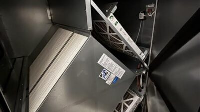
The example office building is 20-story Class A multitenant space developed by a large property manager. The operational technology (OT) systems include HVAC, lighting, access control, security cameras, water and energy metering, elevator controls and internet of things (IoT) systems for occupancy tracking and indoor air quality monitoring.
All systems extend into the tenant spaces, but tenants will provide their own IT infrastructure. Because the building owner’s IT systems will be limited and they have corporate standards for both information technology (IT) and OT cybersecurity, it makes the most sense to combine the IT and OT network infrastructures within the building to save on equipment and cabling costs and simplify the network management.
The first step after making that decision is to determine the size and location needs for this network equipment. In this example, every part of the floor is within a 220-foot radius of the center, so we can efficiently locate a data closet on every third floor to serve the levels above and below them, with a continuous chase connecting all of them. A distributed architecture would be a viable alternative, placing switches in the ceilings for OT systems, but there are too many factors involved with this design to review in this article.
The size of the room will be based on how many racks are needed, which leads us to the next design decisions: wiring topology and wireless infrastructure. We will choose to use ring topology for most devices as a cost-effective option with home-run connections for the most critical pieces of equipment like rooftop units. The IoT systems will be connected through a wireless mesh network but receive power through the lighting infrastructure, so single gateways, typically smaller than one cubic foot, in each data closet will be the only space considerations for wireless OT devices.
From the owner’s cybersecurity standards, we know that a firewall device is only needed in the demarcation room. With this information and knowing that all services/applications will be cloud-based, we can be confident that only one rack is needed per room to serve the OT systems on the network.
The backbone cabling is shared between the IT and OT portions of the network. Typically dictated by the owner or designed by a technology consultant, we would expect this backbone cabling to be in star topology from a main data room on the ground floor with every closet getting 24-strand single mode fiber. From here the engineering design process is more familiar, locating variable air volume boxes, light fixtures, meters and other equipment.
Without additional integration use cases requested, a ARCAT CSI Division 25 specification is not necessary, although it can still be helpful for coordination. Since it is integrated with the IT network, ARCAT CSI Division 27 is the best place to put requirements for all Ethernet cabling that will be used by the controls systems and the same contractor pulling cables for data will pull and terminate cables for IP controls, including any point-to-point cables part of rings.
The low-voltage contractor responding to the Division 27 specifications handling all the cabling will help keep the cable trays orderly and consistent and because the integration scope is limited to the physical infrastructure with the owner managing the software infrastructure the process will be simple enough to manage traditionally without a master systems integrator (MSI).
Overall, this is a straightforward design with IP addresses being one of the biggest coordination items, but with an owner that has standards around integrated networks their IT team will already be expecting it.
How hospital control systems are different
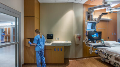
Hospitals are significantly more complex than commercial office buildings, having to adhere to strict codes for building systems and handling sensitive patient information on their networks. With the heightened cybersecurity concerns and large number of OT devices needed, OT networks in hospitals should be separate from the IT network, with just a single point of connection to enable remote access.
The OT network will include all the same systems as the office building, except security cameras will be pulled to the IT network and medical gas added. It is important that any systems with potentially sensitive patient information is properly managed by the IT group to meet HIPAA requirements for data security and confidentiality.
In this example, there will be integrations between the building management system, lighting and nurse call systems to allow patients to control the environment in their rooms. Whereas most of the OT network management for the office building was done remotely by the central property management team, the local facilities group will be responsible at the hospital so we will have to identify spaces outside of data rooms to house OT network equipment.
Ring topology will still be appropriate for many devices, but there will be a larger amount of equipment with built-in IP controls, plus a larger overall number of connected devices, so more ports overall will be needed. Mechanical, electrical or other facility rooms can be good options for wall-mounted racks, but you must ensure the switches used are hardened appropriately for the space they are in and are not too close to sources of electrical interference. In an ideal situation, space is dedicated for OT network closets but with square footage at a premium in a hospital, it can be difficult to convince the owner it is worthwhile.
Segregating the OT network from the IT requires dedicated backbone cabling, so we will need to plan a head end location for a core switch and identify every local switch location on a riser diagram to receive a homerun fiber backbone. Between 12 and 24 strands of single mode fiber would be a good future-proof choice; multimode fiber would be a cheaper option.
Cybersecurity needs will again depend on the owner’s standards, but we would plan to at least have a firewall standing between the IT and OT networks at a single point of connection. Because this network is separate from IT, there is a stronger argument that its requirements including all cabling, network gear, topologies, etc. belong in a Division 25 specification along with the integration use case for patient room environmental controls so that a qualified contractor like an MSI is overseeing the OT network process.
Cabling will still be run by the low-voltage Division 27 contractor, but it would not be responsible for coordinating with the needs of all the trades. Another benefit of having a standalone OT network with a dedicated sub to stand it up is that is becomes easier to accelerate the activation of the OT network, which is necessary for completing the controls systems in time for tests and balance and other commissioning items needed to meet codes.