Electrical engineers sized medium-voltage power conductors at a water treatment plant
Water treatment plant insights
- This article will mainly focus on 2023 NEC Article 315 and its guidelines for Type MV cables for industrial application, particularly for a water treatment plant.
This case study presents the process for sizing medium-voltage (MV) insulated power conductors at a water treatment plant. This does not include the sizing of the equipment grounding conductor, which is in NFPA 70: National Electrical Code (NEC) Article 250.122, nor low-voltage (LV) conductors, included in NEC Article 310. Additionally, not all protective relays, control devices and control wiring are shown. Design topics such as load calculations, protective device sizing, conduit sizing, etc. will not be detailed in this study.
What is a water treatment plant?
A water treatment plant is a facility that improves the quality of water for a specific end-use, such as providing safe drinking water for communities. This process involves the transportation and treatment of large quantities of water, requiring large motors, pumps and other electrical loads. While some of the electrical loads may be indoors, many may be outside. Additionally, some areas of a water treatment plant may have corrosive or dangerous chemicals present.

Water treatment plants are generally large facilities requiring utility power from one or more sources as well as a secondary standby power system. Based on the criticality of the treatment plant, the secondary power source(s) may be portable or permanent and may provide power to only a portion of the facility or the entire water treatment plant.
Based on this information, it can be determined that a water treatment plant is a critical industrial facility with outdoor wet locations and corrosive areas that requires large amounts of reliable power. The wires will often need to be water- and temperature-resistant and housed in a raceway to allow for extra protection from corrosive materials and large machinery.
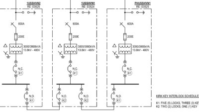
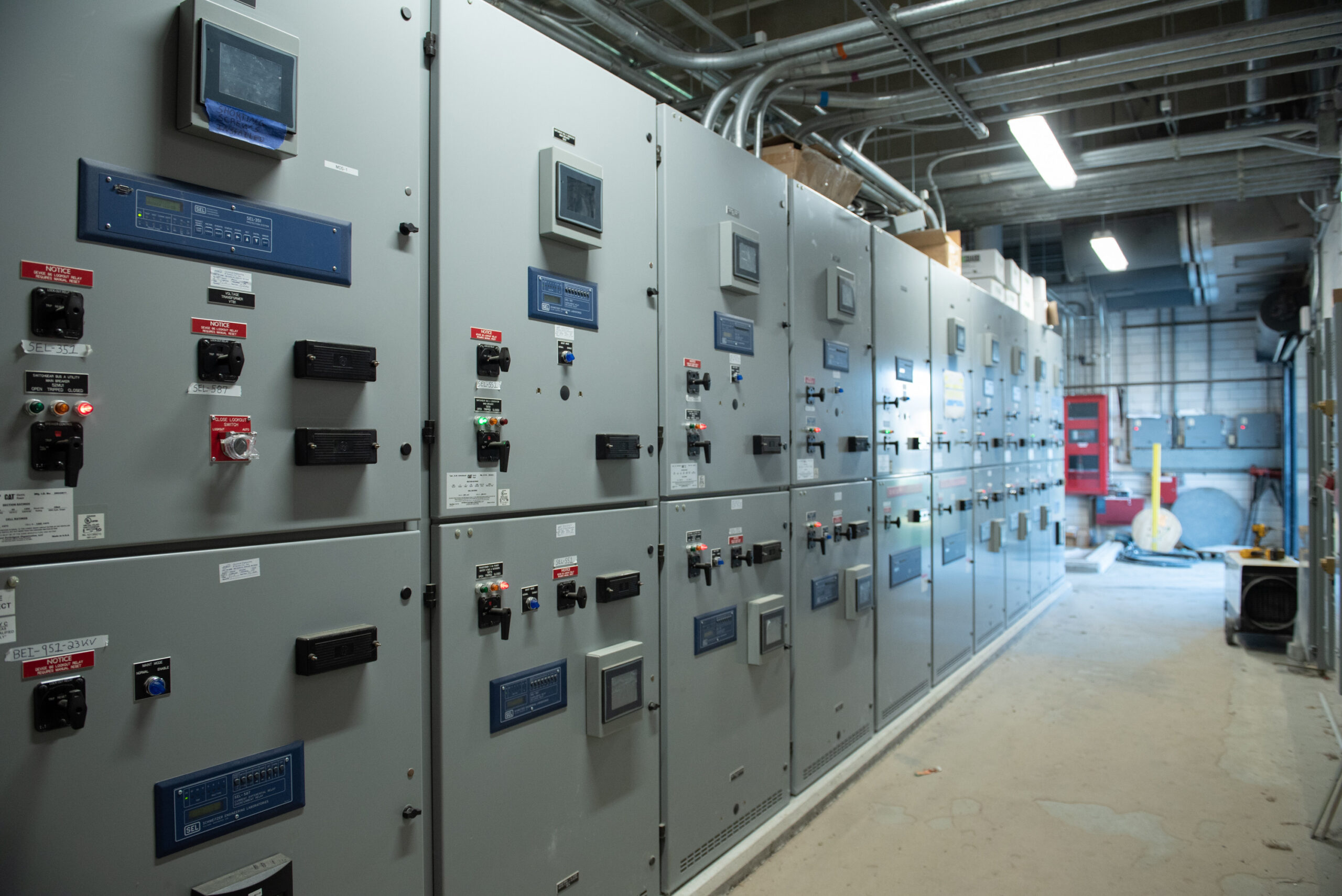
This water treatment plant includes two standby generators connected in parallel to a MV switchgear with a closed transition connection to a single utility source. The switchgear feeds power into two utility switches with a radial loop connection, providing power to several utility transformers powering various buildings and well sites.
Due to the great distances between site locations and the large electrical load demand on the system, MV is the ideal choice. A LV system would require vastly oversized conductors to account for the voltage drop from covering great distances, costing far more than MV conductors. Additionally, it would be difficult to procure electrical equipment rated for the large amperage ratings needed to use LV instead of MV.
Wire types in a water treatment plant
Copper is a common choice for MV cable applications because of its durability and conductivity. However, aluminum is cheaper, lighter, more malleable and generally easier to install. For this plant, copper conductors were the preferred type to specify; however, the local utility required aluminum conductors when connecting to its equipment. When designing, considerations must be made to state/local standards and especially local utility standards when connecting to the local utility’s equipment.
Therefore, aluminum conductors were chosen from the utility power source transformer to the service entrance disconnect and from the MV switchgear to the two utility switches. Copper conductors were specified from the service entrance disconnect to the MV switchgear and from the MV switchgear to the two MV standby generators.
While both 4,160 and 12,470 volts alternating current (Vac) systems are common MVs for water treatment plants, this system’s voltage is 12,470 Vac. Note: Wires come in voltage ratings of 5 and 15 kV.
Per NFPA 70 Article 315.10(A), Type MV cables come in MV-90 and MV-105 based on the maximum conductor temperature. For this application, MV-105 was chosen for maximum conductor temperature capabilities.
For the percent insulation level, 133% was chosen as a conservative safe option ensuring ground faults will be cleared before failure of the cables. Per NFPA 70 Article 315.10(C), a minimum insulation thickness of 220 mils for a 133% insulation level 15 kV cable.
For the insulation type, ethylene-propylene rubber was chosen with a sunlight-resistant polyvinyl chloride cable jacket.
Sizing power conductors
NFPA 70 Tables 315.60(C)(11) and 315.60(C)(12) were used for sizing the conductors. NFPA 70 Table 315.60(C)(11) is for three single-insulated copper conductors in underground electrical ducts, while 315.60(C)(12) is for three single-insulated aluminum conductors in underground electrical ducts. See Tables 2 and 3 for excerpts from each NFPA table. As mentioned previously, both copper and aluminum conductors were used in this project.

Note: Although the MV-105 type cables were selected, the 105°C column of the tables could not be used for sizing the conductors in this water treatment plant. Per NFPA 70 Section 110.40, terminated conductors shall be based on the 90°C temperature rating and ampacities, unless otherwise identified. Therefore, the 90°C columns of the tables was used for sizing conductors in this case study.

Utility transformer to service entrance disconnect
For this project, the total electrical load demand for the system was determined to be 225 amperes (A), requiring a 250 A circuit breaker and disconnect. Therefore, the service entrance conductor (shown as Line 1) must have an ampacity of 250 A or more. Remember, the utility requires aluminum cables for its transformer. Referring to Table 315.60(C)(12), column 5001-35,000 volts (V), MV-90, the wires had to be sized 250 kcmil or larger. For this water treatment plant, three 250 kcmil aluminum wires were selected.
Service entrance disconnect to main switchgear
For the disconnect to the main switchgear (shown as Line 2), copper cables were used instead of aluminum because there was no utility requirement from the service entrance switchgear. Referring to Table 315.60(C)(11), column 5001-35,000 V, MV-90, the wire had to be size #3/0 AWG. For these cables three #3/0 AWG copper wires were chosen.
Main switchgear to standby generators
The standby generators are rated 2,188 kVA, resulting in 101.3 full load amps. For the generators, 125 A circuit breakers were chosen and thus from the switchgear to the standby generators (shown as Line 3), the conductors had to be rated for 125 A or more. Referring to Table 315.60(C)(11), column 5001-35,000 V, MV-90, the wires had to be size 2 AWG or larger. The cables chosen for each generator were three #2 copper wires.
Main switchgear to utility switches


For the switches, the connected loads were determined to be 113 A each, so 125 A circuit breakers were selected. This meant the conductors from the switchgear to the utility switches (shown as Line 4) must be rated for 125 A or more. Additionally, just like the wires for the utility transformer, these wires had to be aluminum because they are connected to utility switches. Referring to Table 315.60(C)(12), column 5001-35,000 V, MV-90, the wires had to be size 1 AWG or larger.
However, the utility required aluminum conductors with a minimum size of #1/0 for standardization and to potentially reduce voltage drop for well sites located far apart. This minimum utility requirement of three #1/0 aluminum wires were selected. Refer to Table 4 for a breakdown of the conductor sizes for each one-line diagram line number.