This outlines the process for choosing EV chargers and selecting the electrical equipment to support the EV charging infrastructure.
The facility is a new water treatment plant with a large fleet of electric vehicles (EVs). EVs on-site will include full-time staff reporting to the plant on a regular basis, staff occasionally visiting to perform work and nonemployee visitors.
The staff reporting to the facility full-time or visiting on a regular basis will be driving fleet vehicles. Fleet vehicles are expected to be made up of 80% to 90% light-duty work trucks and the remainder will be sedans. Altogether, there will be 14 staff members with fleet vehicles; each will be provided with a dedicated EV charging station for full charging capabilities.
To accommodate occasional staff and nonemployee visitors, space will be made for an additional 14 vehicles. It is estimated that people in this group will typically spend 1 to 2 hours on-site and will likely drive an average of 40 to 60 miles to reach the site. It is estimated that most vehicle charging will be performed elsewhere and facility charging will only be required to top off the vehicle’s battery.
Based on use cases and client feedback, it was determined to use direct current fast charger (DCFC) stations for all vehicles; however, the fleet vehicle charging stations would require higher power.
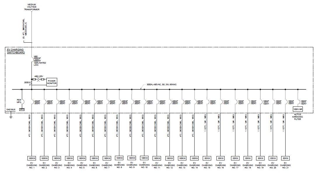
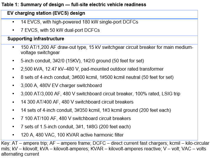
Discussions with the client indicate that the department typically deploys 50 kW DCFC and 180 kilowatt (kW) chargers at other sites. The 50 kW charging station is a dual-outlet format charger. If a single vehicle is charging, it can offer up to 50 kW of power. If two vehicles are charging, it can offer 25 kW of power to each. In total, there will be 14 180 kW charging stations and seven 50 kW charging stations. Most charging is expected to be done during work hours.
A 70% diversity factor will be used for equipment sizing because not all EV charging stations will be used at the same time. Additionally, current EV chargers are rated at a specified peak power level (e.g., 50 or 180 kW). In real-world charging conditions, the peak power transfer is not typically maintained, with the current (and thus power) decreasing over a constant voltage as batteries approach full charge. This charge tapering protects battery longevity and manages the thermals of the charging system, but it also slows the rate of charging when battery levels exceed 80%. This is allowed if a power control system (PCS) is included per NFPA 70: National Electrical Code (NEC) Article 625.42, which allows reduced sizing if controls are in place to limit the overall demand.
With these factors, the amperage draw is estimated to be 2,416 A at 480V with 70% diversity factor. The 180 kW charging stations would draw 217A and the 50 kW charging stations would draw 60A. A diversity factor cannot be used for each charging station. NFPA 70 Article 625 requires an individual EV charging station to be considered a continuous load with electrical equipment sized based on 125% of the demand.
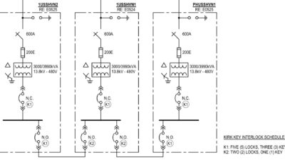
Power will be provided by a dedicated switchboard with no other process loads; therefore, load management is not necessary. The switchboard will be rated 480 volts (V), 3,000 amperes (A) and fed from a 2,500 kilovolt-ampere (kVA), 12.47 kV to 480 V, pad-mounted transformer. The transformer will be connected to a central 12.47 kV switchgear installed on-site.
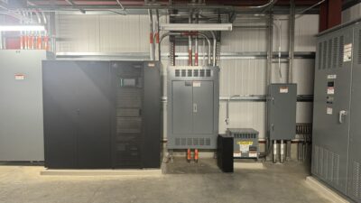
All EV charging stations will be installed at the administration building; to save space, the EV charging switchboard will be installed in the nearby main electrical building. The pad-mounted transformer will be installed outside of the main electrical building. All EV charging stations conductors will be fed 100 feet from the main electrical building EV charger switchboard to a maintenance hole located in the administration building parking lot.
The client does not want to require payment for use of the EV charging stations because the facility is secured with a gate and fence. Only staff and approved visitors will be allowed on-site and permitted to use the EV charging stations. (No communication is required from the EV charging stations. Only power will be provided from the EV charger switchboard.)
A harmonic filter system is required to mitigate harmonic distortion that might originate from operating EV chargers in the facility electrical system. Among the types of harmonic filters available, an active harmonic filter system is recommended. The harmonic distortion from chargers is specified at less than 5% for the 180 kW DCFCs and less than 3% for the 50 kW DCFCs. The recommended harmonic filter is one 120A, 480 VAC, 100 KVAR active harmonic filter for the switchboard bus, which is to be installed in the main electrical building.