Learn about the choices and criteria for the planning and design of mission critical facility switchgear, transformers and UPS
Learning Objectives
- Determine options for mission critical switchgear, transformers and uninterruptible power supplies.
- Understanding voltage levels and standards.
- Review transformer types and the trade-offs of different specifications.
Mission critical facilities typically require electrical engineers to design and specify significant amounts of power to increase reliability, limit outages and provide for redundancy. Common examples of mission critical facilities include hospitals, laboratories and data centers. With the need for extensive power, these facilities often require the engineer to design medium-voltage primary services, primary service transformers, low-voltage distribution gear and uninterruptable power supplies. In some smaller mission critical facilities, the local utility may furnish primary medium-voltage equipment, leaving the engineer to focus on low-voltage systems design.
IEEE defines voltage classifications High-voltage is anything above 69 kilovolts. Medium-voltage systems in the United States typically range from 69 to 5 kilovolts. The most specified and installed medium-voltage equipment within a mission critical facility is either 15 kilovolts or 5 kilovolts rated. Low-voltage in the United States typically ranges from 480 to 120 volts. Most recently, data center equipment has been using 415-volt power to racks.
Medium-voltage primary equipment
In smaller to medium-size facilities, the utility company often provides medium-voltage equipment where required. These maybe located in a special utility vault inside the building or located outside the building. In addition, many owners lack the maintenance personal or contractors qualified to operate medium-voltage equipment.
However, in larger mission critical facilities, it can be advantageous to the facility owner from a cost, maintenance and reliability standpoint to own and operate their own medium-voltage equipment. In selecting primary medium-voltage switchgear there are basically two types of equipment that can be specified: metal clad and metal enclosed.
Metal-clad switchgear is defined in ANSI C37.20.2-2015 IEEE Standard for Metal-Clad Switchgear as metal clad switchgear with the following features:
- Removable draw-out protective devices (breakers).
- Completely enclosed grounded sheet metal compartments for each protective device or control section.
- Stacked protective devices in each vertical section; typically two breakers.
- Automatic shutters to isolate the breaker connections (stabs) from the rear bus.
- Insulated bus and connections.
Metal-enclosed switchgear is defined in ANSI C37.20.3-2013 IEEE Standard for Metal-Enclosed Interrupter Switchgear as metal enclosed switchgear with the following features:
- Fixed mounted switches with power or load interrupter fuses.
- Noncompartmentalized single vertical sections (one fused switch per section).
Metal clad switchgear is generally viewed as the preferred selection for most mission critical operations due to the safety of enclosed compartments and ability to remove breakers for servicing. The ability to automate breakers and reclose after trips is also an advantage. Metal enclosed switchgear offers simplicity of operation, fast acting fuses, low maintenance and often costs half as much as metal clad switchgear.
Primary transformers
For projects receiving primary service from the utility company, local use power will need to be derived from medium-voltage transformers. Transformers are available in multiple types, ratings and packages, and have advantages depending on the location installed and intended use.
The two main types of transformers are dry-type and liquid-filled. Dry-type transformers are typically installed indoors and liquid-filled transformers are typically installed outdoors, but both types can be installed in either location with proper consideration of the installed environment.
Dry-type transformers are available in multiple types. Generally ordered by increasing cost and resiliency, these types include open wound, vacuum pressure impregnated, vacuum pressure encapsulated and cast coil. These configurations are called dry-type because they use air to cool the windings. An open wound transformer only has a baked varnish coating to protect the windings from its environment. VPI and VPE transformers start out as open wound but then are either impregnated with a polyester resin or fully encapsulated with a silicone resin under vacuum pressure to draw the material into the windings. These two methods offer increased resistance to dusty or humid environments in the case of VPI or harsh and hazardous environments in the case of VPE. Cast coil transformers take things one step further and cast the windings in an epoxy resin using a mold to fully encapsulate them. Cast coil transformers are recommended for extreme environments.
Liquid-filled transformers use an insulating liquid such as oil or dielectric fluid to cool the coils instead of air. For these, the windings are enclosed in a tank and submerged in the liquid. The tanks are sealed, but can leak or rupture due to age or excessive stress. As such, when used within a building, nonflammable liquids shall be specified and spill containment such as drains or curbs should be used when appropriate. The 2020 edition of NFPA 70: National Electrical Code Article 450 requires that a “liquid confinement area” be provided when less-flammable or nonflammable liquid-filled transformers are installed indoors. It should be noted that only transformers rated 35 kilovolts or less can be installed indoors per NEC 450.23. When installed in transformer vaults meeting the requirements of NEC 450 Part III, drains shall be provided to collect any accumulated liquid.
When specifying transformers, the first thing to consider is its load rating. This is typically rated in kilovolt-amperes and can be determined by load calculations. Some transformers may list multiple load ratings. This usually includes a base rating when cooled by ambient air and then possibly an increase rating between 20% and 50% higher when cooled with the assistance of fans. It should be noted that fans can fail so loading a transformer consistently to its fan-assisted rating may cause extra stress on the transformer and may lead to decreased equipment life.
The second thing to consider when specifying transformers is the insulation class. This is described as the maximum allowable winding (hot spot) temperature of a transformer to have a normal life expectancy and is listed as a temperature in degrees Celsius. The insulation class is also often described as the temperature rise above ambient.
For example, a transformer with an insulation class of 130°C will have a temperature rise of 80°C over an ambient of 40°C. The extra 10°C is a factor to account to local hot spots. Exceeding this temperature is possible and won’t necessarily result in an equipment failure, but it will likely impact the service life of the transformer. Dry type transformers are typically rated with 80°C, 115°C or 150°C rise. Liquid-filled transformers are typically rated for 55°C or 65°C rise.
At a fixed insulation class, higher temperature rise will yield a longer life for your transformer, but will also be more expensive. Most dry-type transformers are constructed with 220°C insulation regardless, so the opposite is true. For critical applications, going with a lower temperature rise dry-type transformer can extend the life of the transformer.
Where to locate a transformer and in what arrangement is heavily impacted by site conditions. When space inside the building is a limiting factor, pad-mounted installations are common, and an underground vault is also an option. Clearances, accessibility and maintainability should be considered when locating a transformer outdoors. For critical applications, the engineer should pay careful attention to accessibility as damage could be caused by vehicles, intruders or nature depending on accessibility of the location.
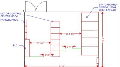
For indoor locations, liquid-filled transformers are typically installed in transformer vaults, but dry-type transformers are regularly installed directly in the main electrical room. Small- and medium-sized transformer are typically installed on concrete pads adjacent to the low-voltage distribution equipment, but larger transformers can be installed in direct contact with primary overcurrent protection or isolation and secondary switchboards or switchgear in one long lineup. Called unit or unitized substations in this configuration, the primary and secondary connections of the transformers can be close-coupled to the busing in the primary and secondary equipment. This arrangement is both a cost savings and space savings option and can offer increased reliability.
Every mission critical application will have different demands of a transformer. Where extra capacity maybe needed for peak load demand such has N+1 failure or future load growth the addition of fans can allow for up to 33% increased capacity. For hospitals, airports or other critical civil or institutional locations, cast coil may have a shorter life than a VPI as the regularly load variability can cause degradation of the encapsulating epoxy over time. For critical industrial applications, VPE or cast coil offer increased resilience to overloads and harsh environments.
Low-voltage switchgear
Engineers, architects, contractors and facility owners often use the terms “switchboard” and “switchgear” interchangeably when referring to 480-volt (600-volt class) circuit breaker distribution equipment. But there are notable differences in configurations, components, standards, applications, reliability and selection criteria between these two types of power distribution equipment (see Table 1). While switchgear is the typical choice for primary services in mission critical facilities, it is important to understand the differences and where switchboards might be used.
A major difference between switchboards and switchgear is the type of breakers used. The basic types that we are concerned with are: sealed, semi-open and open types. Specifically, these are called molded case, insulated case and power circuit breakers.
Molded case circuit breakers: MCCBs are the most common, used in all types of low-voltage switchboards and panel boards. One will find these breakers in ratings from 15 to 3,000 amperes. The breaker mechanism is totally sealed within external molded case. If the breaker has a failure or problem, it must be replaced. These breakers are typically bolted onto the bus or may have plug-in designs. The removal or addition of MCCBs to a switchboard should only take place with the switchboard power turned off.
Insulated case breakers: ICCBs are a type of MCCB designed to provide features typically available in power circuit breakers. Typical ratings range from 400 to 5,000 amps. These breakers are available as options in switchboards and can be fixed or draw-out design. Designed to the same standards as MCCBs, they provide access to replaceable parts such as contacts.
Power circuit breakers: Typical ratings range from 800 to 5,000 amps. PCBs are designed and tested under much different standards from MCCBs or ICCBs. PCBs are connected to the bus in a draw-out design, allowing the breakers to be withdrawn partially or fully while the entire switchgear is powered on. PCBs have numerous components that can be inspected and replaced, such as contacts, pole assemblies and arc chutes.
Switchgear, switchboards and associated breakers are designed and tested to different standards as shown in Table 1, resulting in different capabilities and application considerations.
Application considerations
How much continuous current can you put on a 400-ampere circuit breaker? It depends on the breaker. With MCCBs and ICCBs, the breaker is typically rated for only 80% of its capacity within a switchboard or panel board. In this case, you could put no more than 320 amperes continuously on that breaker. This is a limitation not everyone is aware of. It is possible to specify optional 100% rated MCCBs and ICCBs in some frame sizes. PCBs are 100% rated as standard (see 2020 NEC Article 210-20).
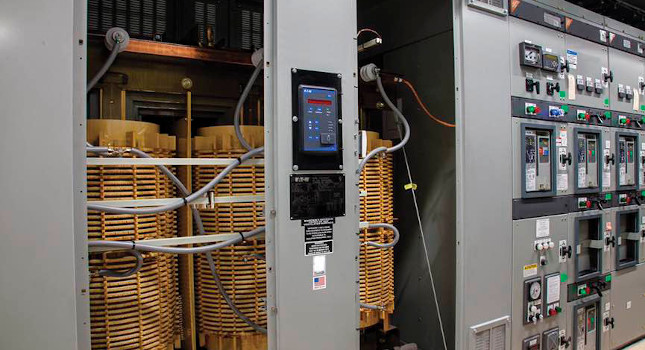
Figure 5: An example arrangement of modular uninterruptible power supply equipment and its associated input and output buses and batteries are contained within a common lineup. This arrangement allows for additional UPS units to increase capacity. Courtesy: SmithGroup[/caption]
Second, the ability to have draw-out breakers also permits repair, inspection and replacement of a breaker while the rest of the switchboard or switchgear continues to operate. Third, PCBs and, to a lesser extent, ICCBs, have exposed and accessible parts that can be regularly inspected and replaced without having to buy an entirely new breaker. Lastly, PCBs have a more rugged construction and can handle more closing and opening operations, including faults and provide for automatic remote control for transfer schemes.
Switchboards have a place in mission critical facilities, most typically downstream in the electrical distribution system feeding mechanical systems such as pumps and precision cooling units found in data centers. A benefit to switchboard is their ability to have ratings of 1,600 amperes and higher where typical panel boards are limited to 1,200 amperes, making them a good choice for localized high power demands in mission critical projects such as UPS systems.
UPS
An in-depth discussion of UPS systems is beyond the scope of this article, but several fundamental characteristics should be understood for their applications in mission critical systems.
The most basic configuration of a UPS consists of a rectifier that converts alternating current power to direct current power, batteries that provide backup DC power upon loss of AC and an inverter that converts DC back to AC Power. Also, a static bypass is usually included for any failures in the rectifier or inverter components.
In mission critical applications, additional features are considered for UPSs. These include maintenance bypass systems, multiple AC inputs and multiple paralleled rectifier/inverter modules. These parallel modules are often configured in what’s called an N+1 configuration where any one module can fail yet still provide the capacity needed for continuous power.
The typical battery choices for UPS systems include flooded cells, valve regulated lead acid and lithium ion batteries.
Flooded cell batteries (or wet cell batteries) have a long history in UPS systems; they usually have very long life, but require frequent maintenance such as fluid replacement, spill containment provisions and present off-gassing issues and special ventilation systems. Because of these issues they have faded from popular use in UPS systems
Valve regulated lead acid batteries are sealed and considered maintenance-free. The electrolyte in the battery is immobilized using either gel or absorbed glass matt. VRLA AGM batteries are the current default standard for data center UPSs due to improved safety and low maintenance. However, the battery life is often in the 5- to 10-year range and the batteries required a very stable room temperature around 77°F to avoid reduced lifespan.
Lithium ion batteries are a newer technology that offers significant improvements over VRLA batteries, including longer life and tolerance to higher room temperatures. When first introduced, the cost increases where notable but have steadily decline. One area of debate with lithium ion batteries is their safety, and new standards such as NFPA 855: Standard for the Installation of Stationary Energy Storage Systems address the special accommodations for lithium ion batteries.
Mission critical facilities require numerous considerations for designing and specifying switchgear, transformers and UPS. This article highlights some of the primary types, choices and criteria for the engineer to review during planning and design stages.