Selecting a booster pump is unique to each building. Considerations for future building growth and changing infrastructure contribute to providing a future-ready and dependable system.

Learning objectives
- Learn the common types of domestic water booster pumps available and some benefits of each type.
- Identify domestic water booster pump design criteria and common sources of pressure loss to a domestic water service.
- Understand the variables that impact pressure calculations for domestic water system design.
Pump insights
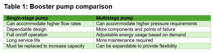
- Booster pump systems for high-rise buildings are designed to address challenges of water pressure and flow, with single-stage pumps suited for high-flow applications and multistage pumps offering energy efficiency, redundancy and flexibility for variable demand.
- Every booster pump must meet strict code requirements, including accessibility for pump maintenance and compliance with potable water standards, ensuring the pump delivers reliable performance throughout the building system.
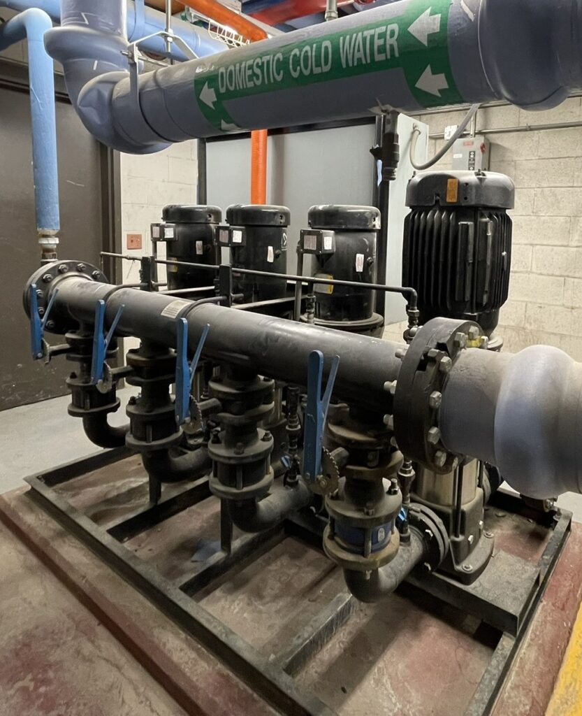
Booster pumps serving domestic water and fire systems in high-rise buildings are designed for specific challenges. These challenges include building height, available water pressure and ensuring the domestic water system works properly.
High-rise buildings are defined by the International General Code Development Committee. The definition in Section 202 of the 2024 International Fire Code (IFC) states that a high-rise building is a building with an occupied floor more than 75 feet above the lowest level of fire department vehicle access. The definition of a high-rise building can be amended by any local authority having jurisdiction, so it is important to confirm the definition for each project location.
This article will utilize the IFC definition for high-rise buildings and focus on buildings between four and 20 stories tall. The design strategy for buildings with more than 20 stories is different to accommodate the pressure rating and performance of common pipe materials. There are multiple types of booster pumps, and each has specific benefits for a high-rise building application.
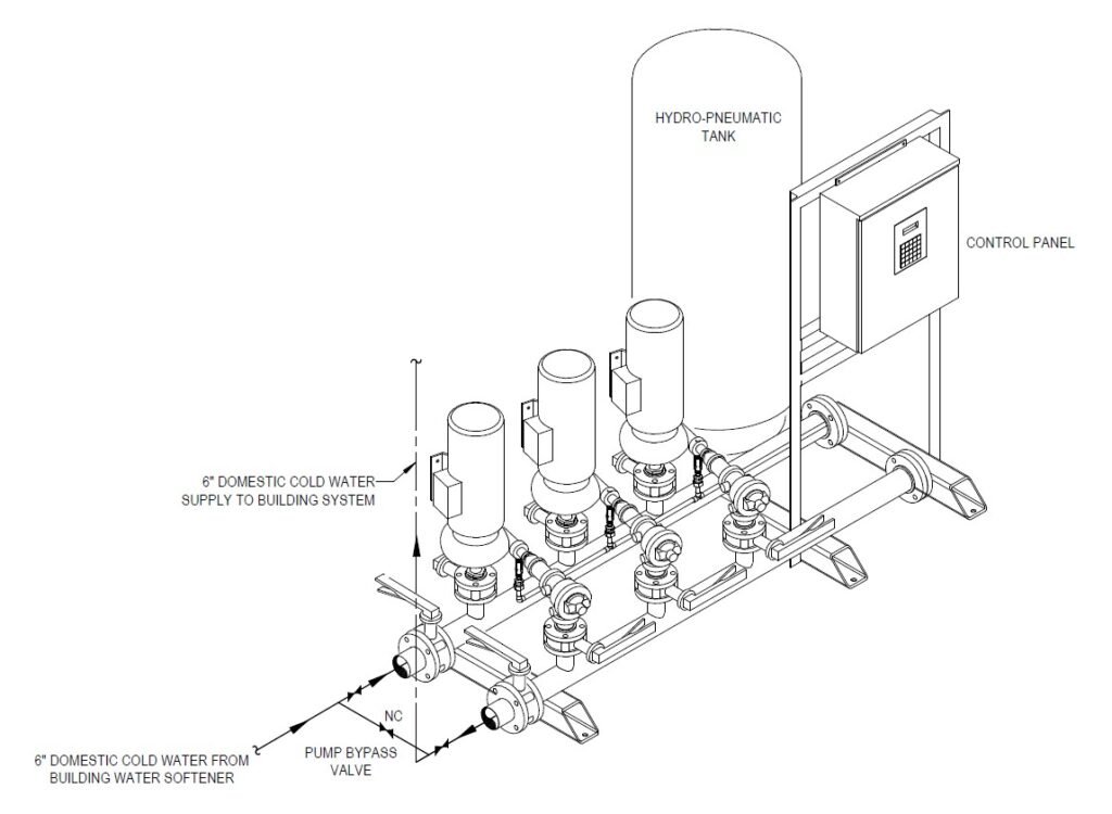
There are two categories for booster pumps: single-stage and multistage. A multistage pump is two or more impellers working in series on the same shaft connected to the motor, while a single-stage pump is a single impeller controlling the motor. In a multistage pump assembly, each pump boosts the pressure by a specific amount, and when they work in series, the output pressure is the design demand. The pumps also work together, controlled by a variable frequency drive located within the control panel to accommodate the variable flow rate to match the building demand.
A multistage booster pump is beneficial for a high-pressure application. Multistage pumps typically use less energy and are easier to maintain because smaller pumps can be changed out. In many cases, a multistage pump assembly has N+1 redundancy (where N is the total number of pumps required to meet the system demand and 1 is an equal-sized spare pump provided), which allows the removal of a pump for maintenance without impacting the building system performance.
Finally, multistage pumps provide flexibility for both flow and pressure, which is key for buildings that have a variable demand or plans for future growth. Multiple pumps can work together to share the demand equally or be designed to work in a specific sequence.
A single-stage booster pump is beneficial for a higher flow application. Single-stage pumps are also dependable and have a long service life. This is beneficial for systems such as fire protection, where durability and dependability are critical.
International Plumbing Code requirements
Every domestic water booster pump must meet specific code requirements. A few sections in Chapter 6 of the 2024 International Plumbing Code (IPC) are important when designing booster pumps. Section 602.3.5 of the IPC states that all booster pumps must be rated for the transport of potable water and that every booster pump must have access to pump parts for repair. For domestic water, this means meeting the National Sanitation Foundation (NSF) 61: Drinking Water System Components – Health Effects requirements.
When looking at pump selections, this means ensuring that the pump is either a split-case or a skid-mounted assembly. With a split case, either vertical or horizontal, the pump enclosure can split apart along an axis to provide access to the pump components for repair. Multistage pumps are open, and each pump can be removed, so access to the pump assembly components is available, while single-stage pumps must be a split case type pump to provide access.
IPC Section 604.3 states that the pipe sizes and water distribution system must be sized based on peak demand for both flow rate and pressure for the system. For domestic water systems, the required pressure is based on the highest elevation of the most remote fixture and the type of plumbing fixture the booster pump is serving. Common required pressures based on fixture type can be found in IPC Table 604.3.
Certain buildings, like health care facilities, may include equipment that requires higher flow rates and pressures than plumbing fixtures, so it is important to understand the building’s system characteristics. During design, the specific flow and pressure demand should be used for system calculations to ensure that an adequate water flow rate and pressure are available at each location or fixture in the system.
On the incoming side of the booster pump, we must design for the minimum pressure available from the utility as required by IPC Section 604.6. Booster pumps are installed when the incoming pressure is insufficient to meet the building requirements.
It is equally important to understand the residual pressure available from the utility on the incoming side, as it is the pressure required on the outgoing side to adequately serve the building. In many cases, the utility is a system of street mains, but it could be a different source, such as a well or water storage tank, so it is also important to identify and confirm your source location and type.
The domestic water system within any building has limitations to consider when it comes to increasing the system pressure. IPC Section 604.8 states that the maximum allowable building water pressure is 80 psi static pressure at the fixture. This section in IPC states that where the pressure is anticipated to exceed 80 psi, a water pressure reducing valve is to be installed that conforms to American Society of Safety Engineers Standard 1003, which includes a strainer.
For high-rise buildings, this maximum allowable pressure is an important consideration. When the criteria for the booster pump is to serve the most distant fixture, the fixtures on lower levels will experience higher pressures that can, in some cases, exceed the maximum allowed pressure. To accommodate this when designing a domestic water booster pump for a high-rise building, pressure zones are almost always required.
Pressure zones and multiple booster pumps
Pressure zones can reduce the flow rate required for each of the zone booster pump(s) and reduce the number of pressure-reducing valves required to serve the fixtures on lower levels of the building. To determine where to divide the building domestic water system into zones, start with the required pressure at the maximum height above the source and the available water supply source residual pressure at the building peak flow rate. The available residual pressure also informs the design for how many levels of the building can be adequately served from the utility pressure. In some applications, where the required pressure at the highest level creates a system that exceeds 80 psi at multiple levels of the building, multiple pressure zones and multiple pressure booster pump assemblies are best practice.
Multiple booster pump systems can increase the building system flexibility for future available pressure and simplify the domestic water system maintenance and controls. IPC Section 604.8 identifies additional requirements that are to be considered when including water pressure reducing valves or regulators as needed in a high-rise domestic water system.
Booster pumps are also used for fire suppression systems that require fire pumps. Similar to domestic water, the system water source is frequently a street main supply, but it is important to confirm the system source to ensure the design can accommodate the available pressure. Single-stage pumps are more commonly used for fire systems. Single-stage pumps also operate with a set flow rate and pressure that match the steady-state conditions of a fire water system. Most importantly, single-stage pumps are dependable and have a long service life because they have fewer components that require maintenance and a simplified path for water to flow through when in operation. These qualities are important to consider when selecting a required booster pump for a life safety system.
Single-stage pumps
Single-stage pumps provide many benefits applicable to a high-rise building. First, single-stage pumps are capable of increasing water pressure at high flow rates, like those required for a standpipe system. The maximum allowable pressure for a fire water system is 175 psi for hose connections. Similar to domestic water in high-rise buildings, where the supply pressure exceeds 175 psi on any of the lower levels, a pressure-reducing valve must be installed. Unlike domestic water systems, designing pressure zones to serve multiple floors cannot be utilized with the same vertical standpipe. NFPA 14: Standard for the Installation of Standpipe and Hose Systems Section 10.5.1.1 states that each vertical standpipe system zone must have one or more of the following components:
- Connection to a fire service main or utility.
- Separate fire pump.
- Separate outlet from a multistage multiport fire pump.
- Separate water storage tank.
NFPA 14 Section 10.2.4 describes the maximum allowable pressure at the standpipe hose connections. The maximum allowable pressure is 175 psi for the safety of firefighters and people utilizing the system. The minimum pressure required at the hydraulically most remote hose connection is dependent on the type of standpipe system installed for the specific type of building.
Each building design needs to determine the available incoming water pressure. A fire flow test can be performed, and the data from that test can determine and design the booster pumps required for a building’s fire water and domestic water system. NFPA 291: Recommended Practice for Fire Flow Testing and Marking of Hydrants provides guidance for how to perform the fire water flow test. Sections 4.4.5 and 4.4.6 state the number of fire hydrants to be used for the flow test. The number depends upon the strength of the distribution system and the distance from the test location. The flow test must utilize enough hydrants for at least a 10% reduction in pressure.
The result of the flow test includes multiple pieces of information. The first is the static pressure. The static pressure is the pressure that exists in the distribution system when no hydrants are flowing. The next piece of information is the residual pressure, which is the pressure that exists in the distribution system when water is flowing from the hydrants during the flow test. The flow test can be performed at any time, so it is important to note the time and date on the flow test data.
Section A.4.3.1 in NFPA 291 states that the flow test does not need to be conducted during peak demand time. If a flow test is performed in the morning, then more pressure may be available compared to the middle of the day. Factors such as irrigation or temporary higher demand in surrounding buildings can significantly impact the available pressure.
Section A.4.15.1 states that the data should not be more than five years old because conditions can change over time. The two main conditions that may change are the condition of the distribution system pipe and the system demand. Both can change significantly over time. Because the design and construction process can take multiple years to complete, it is important to have a flow test performed during design and prior to equipment submittal and installation. The area surrounding a building site can develop significantly during design and construction, and the state of infrastructure may also change.
With this information, the next step is to utilize a hydraulic graph to determine how much pressure will be available at the specific building flow rate. A hydraulic graph is unique because it is a logarithmic graph specific to determining the flow and pressure relationship.
Creating a campus plan
Considerations for a campus master plan and future surrounding infrastructure capacity is best practice when designing a central plant system. Specifically, high-rise buildings with plans for additional vertical expansion could have significantly different available pressure at the time of the vertical expansion. One strategy for future vertical expansion and unknown water pressure is to provide space and connections for a future booster pump from the water entrance downstream of the building backflow preventer. This strategy is beneficial when the vertical expansion planned is a significant portion of the building, and when the timeline for the vertical expansion is unknown or more than five years in the future. Space for future equipment provides the most flexibility and the lowest initial cost.
Another strategy for future planning a high-rise building is to provide a booster pump adequately sized for the full known build out and pressure reducing valves for the lower levels as needed. This strategy is beneficial when a project has limited mechanical space or when vertical expansion is planned to be designed and constructed in the near future. This strategy is also beneficial for projects with low available water pressure, because a booster pump assembly is necessary to serve the building. There is a higher initial cost with a booster pump sized for the full build-out, but the building system will need minimal modifications with the future vertical expansion.
Finally, future vertical expansion and unknown water pressure can be designed for with a multistage expandable pump. By leaving space for additional pumps on the pump skid assembly, the system can be adjusted in the future to the additional demand and available incoming pressure. This strategy is beneficial for projects with shell space that is unknown within the building or for future vertical expansion that could have a significantly higher demand and pressure requirement. This strategy is also beneficial for projects with limited mechanical space, because the additional pumps will be incorporated into the pump skid instead of requiring additional space when expanded. When an expandable booster pump assembly is provided, the pipe sizes and controls have capacity installed for the future with the base design products, and the future modifications are minimal. An expandable pump assembly provides flexibility and a lower future cost as well as minimal disruption to the building system when the additional pumps are installed.
Domestic water pumps
Domestic water booster pumps for high-rise buildings must also be designed to overcome the pressure losses from piping and equipment in the system upstream to the booster pump assembly. The first component of a building water system that can contribute to pressure loss is the water service pipe. This applies to both domestic and fire water.
The pressure loss incurred is based on the flow through a specific pipe size serving the building and accumulates per foot of pipe. In most cases, the pressure loss for the service pipe is not significant, but it must be calculated and considered. The second component that contributes to pressure loss is the backflow preventer. The pressure loss through the backflow preventer assembly depends on the model number and flow rate, and it can be found from the manufacturer’s published information. Typically, the loss through a backflow preventer is 10 psi.
A pressurized water storage tank can also contribute to pressure loss to the system. Typically, the loss through a water storage tank is five psi. One of the most significant components in a building’s water system that contributes to pressure loss is the water softener. Because water softeners have a maximum allowable pressure for the equipment, it is best practice to put the softener system upstream of the booster pump in a high-rise building. In most cases, the pressure required for a high-rise building exceeds the allowable pressure for the water softener assembly.
By putting it upstream, the softener system is protected and efficiently serves the building. A water softener assembly has a pressure loss at continuous flow and peak flow. Both pressure loss values can be found in the manufacturer’s published information.
In most cases, the pressure loss through a water softener at peak flow is 25 psi, so it can significantly change the booster pump design. The booster pump is sized with the peak flow pressure loss from the water softener as a conservative approach because the flow demand is variable in a building’s domestic water system and can change over time.
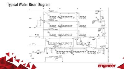
Finally, the water meter can also contribute to pressure loss to the system. The pressure loss from the meter depends on the meter size and flow rate, but in most cases, this is 10 psi. A flow diagram of all the equipment included in your domestic water system can help ensure that all the pressure loss contributors are accounted for, and we know the incoming water pressure to design for at the booster pump.
The incoming water pressure available at the booster pump should be compared to the selected booster pump’s net positive suction head required (NPSHr), or the minimum pressure required on the incoming side of a pump, to avoid cavitation. The NPSHr value is specific to each pump and can be obtained from manufacturer data. Factors for calculating the NPSHr value include absolute pressure, vapor pressure, liquid temperature and specific pressure losses through the pump components.