Designing mechanical systems for cryogenic electron microscopes in cancer research requires precise attention to operational details and performance standards to ensure both project success and sustained high-resolution imaging.
Learning objectives:
- Gain insight into the stringent requirements governing technically sensitive equipment in cancer research.
- Understand the key challenges involved in achieving compliance with these demanding standards.
- Learn about an effective HVAC system approach that supports success in critical performance applications
Laboratory insights
- Cryogenic electron microscopes require highly specific environmental conditions to function properly and efficiently.
- Designing laboratories in a retrofit building project presents unique challenges with space considerations, existing mechanical systems and vibration concerns.
Over two decades ago, a child was diagnosed with bone cancer in the femur at an early age, requiring hospitalization and treatment. At that time, cancer research and treatment options were far less advanced than those available today. Modern advancements in research technology have significantly improved the landscape of cancer treatment. Breakthrough equipment now allows scientists to examine cancer cell replication at the molecular level in greater detail, unlocking new possibilities for drug discovery and offering promising strategies to prevent or halt the progression of this disease.
As a mechanical engineer with a strong interest in the technical aspects of the field, this opportunity to design the mechanical systems supporting a cryo-electron microscope (cryo-EM) research facility presented a valuable opportunity to engage in a highly challenging and rewarding endeavor. For those unfamiliar with similar work, this type of project involves meeting stringent environmental requirements, overcoming complex heating, ventilation and air conditioning (HVAC) challenges to maintain compliance and understanding key considerations essential for the successful design of future cryo-electron microscope research facilities.
In 2018 and 2024, a leading pediatric cancer research center completed projects to install multiple advanced cryo-EMs. These powerful tools allow scientists to see extremely small biological structures in 3D, down nearly to the level of individual molecules. This detailed view helps researchers better understand how proteins function, how healthy and diseased cells differ and how to potentially stop the spread of cancer cells. Only a couple of institutions in the United States are believed to have similar research capabilities.
The initial 2018 programmatic layout for the cryo-EM center included two microscopy suites, a grid clip (specimen preparation) room and associated anterooms, totaling approximately 3,500 square feet. The selected location was an existing basement level, formerly occupied by administrative functions. This strategically chosen location enabled physical and structural isolation of the cryo-EM systems from the rest of the building, minimizing vibration transmission that could degrade imaging resolution.
To achieve this, the existing structural slab was excavated, and a new, independent structural foundation was constructed. The microscope systems were mounted on a dedicated concrete slab supported by vibration isolators to ensure mechanical and acoustic decoupling from the main building structure.
In parallel with the design of new HVAC systems required for the specialized environmental demands of the microscopy suites, a comprehensive assessment of the building’s existing mechanical infrastructure was conducted. The analysis aimed to determine whether the current systems could support the thermal, clean air and humidity control needs for the cryo-EM systems, and whether new infrastructure would be necessary.
It was determined that several elements of the current system did not meet the strict environmental specifications provided by the equipment manufacturer. For example, conventional variable air volume systems with reheat and two-by-two diffusers produced air velocities exceeding allowable limits for cryo-EM imaging environments. Additionally, the existing chilled water-cooling coil system lacked the moisture removal capacity for humidity control necessary for sample preparation in the grid clip room.
A critical factor to address these challenges was the review of the microscope equipment vendor’s pre-installation specifications. These documents provided essential performance criteria, allowing the engineering and architectural teams to select HVAC solutions tailored to the system’s sensitivity to temperature fluctuations, humidity, airflow patterns and vibration.
Key functional spaces within the program include the cryo-EM suites, grid clip room and a shared vestibule that functions as a transitional buffer zone. Each space is subject to distinct environmental parameters, but must operate together to ensure overall system integrity. In particular, the grid clip room, where biological specimens are prepared for imaging, demands exceptionally low humidity levels to prevent the formation of ice crystals during cryogenic freezing.
Temperature and relative humidity (RH) requirements within the room meant maintaining 72°F and below 20% RH. Failure to meet this criterion would compromise sample integrity and image clarity, impeding the research objectives.
Grid clip room criteria informed the HVAC approach. Temperature and RH requirements within the room were necessary to maintain 72°F and below 20% RH. Though it was necessary to maintain an environment with this low of RH, static electricity for slide preparation was not a concern for the users.
In a cryo-EM specimen preparation room, stringent control of environmental conditions — particularly temperature and dry RH — is critical to preserving sample integrity and ensuring high-quality transformation of a substance into a glass, or a non-crystalline solid. Exposure to even modest levels of ambient moisture can lead to the formation of crystalline ice, ice contamination or uneven sample thinning, which compromise structural resolution.
The temperature in the grid clip room should typically remain stable between 68°F to 72°F to ensure consistent physical handling conditions and prevent condensation. However, relative humidity should be kept low — often below 20% — to minimize the risk of airborne water vapor condensing on cold surfaces such as plunge-freezing apparatus or grids exposed during blotting and transfer. Excess humidity can interfere with rapid vitrification by introducing water crystals, while dry conditions help preserve samples and reduce contamination from frost.
Achieving and maintaining such dry conditions requires robust HVAC systems, often supplemented with industrial-grade dehumidifiers and sealed room designs to limit moisture ingress. Continuous monitoring of temperature and RH is essential. Strict adherence to these environmental controls enhances reproducibility and ensures the optimal preservation of ultrastructural details in cryo-EM analysis.
Knowing that a typical chilled water air handling unit (AHU) that delivers 50°F leaving air temperature off the cooling coil is not capable of delivering the necessary dry air requirements for the space conditions, we drew from our experience with ice rinks to help inform this decision and decided on a desiccant unit application.
Using a desiccant dehumidifier to dry a space — such as a cryo-EM specimen preparation room — presents several technical and operational challenges. While desiccant dehumidifiers are effective at maintaining very low RH levels, particularly in cooler environments, their deployment in a controlled laboratory setting involves careful planning and maintenance.
Heat management in the laboratory
Desiccant dehumidifiers function by passing air through a rotating wheel coated with a silica gel, which absorbs moisture. To regenerate the desiccant, hot air is used to drive off the collected moisture. There are two separate air streams: the process air side and the regeneration side. This regeneration process generates significant heat for both airstreams, which must be managed to prevent unwanted temperature fluctuations in the controlled space.
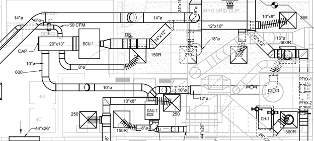
Excess heat from the dehumidifier can interfere with temperature control and may necessitate additional cooling infrastructure. Rejecting the hot, moist airstream off the regenerative side of the desiccant wheel was done by discharging it into the large return duct main right at the riser. The process airstream required some form of post-cooling due to elevated discharge temperatures. There was not a small package system for 600 cubic feet per minute (cfm) of air that provided both desiccant and post cooling. So, a chilled water fan coil unit was installed that mixed the hot process dry air with house ventilation air to provide post-cooling and comfort to the slide prep room.
Air exchange and pressure control
Desiccant systems require a separate air stream for regeneration, which often involves venting hot, moist air out of the room. This airflow can create pressure differentials that compromise room sealing or introduce unfiltered air, potentially affecting sample sterility and environmental stability. Maintaining positive or neutral pressure in the room while operating a desiccant system may require additional air balancing and integration with building HVAC systems. Locating this unit within the mechanical room and using the house air serving this room accommodated for that potential pressure offset.
Space and installation requirements
These units are generally larger and more complex than standard dehumidifiers. They require ductwork, heat exchangers and venting systems that must be carefully integrated into the room’s infrastructure. For retrofitting existing labs or tight prep rooms, space limitations and structural constraints complicated installation.
Maintenance and reliability
Desiccant systems involve moving parts, high temperatures and exposure to moisture — all of which contribute to wear and tear over time. Regular maintenance is required to ensure consistent performance, including checking desiccant rotor condition, inspecting seals and maintaining heaters and blowers. Inadequate maintenance can lead to degraded humidity control or equipment failure.
Despite these challenges, desiccant dehumidifiers remain one of the few reliable options for achieving ultra-dry conditions in sensitive environments. However, their successful use depends on careful environmental design, ongoing monitoring and coordination with other systems to maintain the stable conditions required for cryo-EM specimen preparation.
In selecting the (DAU-1) unit, the system needed to deliver as little as 17.5 grains/pound of moisture to the room. This met the space requirements, allowed for the absorption of any moisture given off by the occupants and kept the room below 20 RH. Finding space above the ceiling for the desiccant unit was a challenge due to its 32-inch height. In the end, it was suspended in an adjacent mechanical room where it could sit lower than the typical ceiling grid and then routed the discharge duct over to a fan coil unit.
Cryo-EM laboratory room criteria
The cryo-EM room criteria by far had the most stringent requirements. Designing the mechanical HVAC systems for a cryo-EM facility requires a high level of technical engineering precision. Cryo-EM microscopes are extremely sensitive instruments that demand tightly controlled environmental conditions, often beyond standard laboratory specifications. The mechanical system must support stable temperature, low vibration, stable humidity control, clean air quality and isolation from electromagnetic and acoustic disturbances.
Here’s a breakdown of the key engineering considerations:
Temperature control: Cryo-EM instruments are highly sensitive to thermal fluctuations, which can cause mechanical drift, image distortion and misalignment over time. The HVAC system must:
- Maintain a room temperature between 6°F to 71.6°F, with a stability of ± 1.8°F over 24 hours.
- Use low-velocity displacement ventilation, chilled beams or chilled radiant panel systems to prevent drafts and temperature gradients.
Relative humidity control: The microscope rooms’ moderate RH (40%–50%) is typically maintained to balance corrosion protection with static control.
- Humidity control is achieved via the AHU, provided through the ventilation air. No source of moisture or human occupants residing in the room during testing.
- Use of reheat coils allows finer modulation of constant temperature from a constant air volume box and maintains RH.
Vibration isolation
Mechanical vibrations, even from building systems or foot traffic, can severely impact cryo-EM imaging.
All mechanical equipment (fans, compressors, pumps) must be vibration-isolated using spring mounts, inertia bases and acoustic pads.
Ductwork should use flexible connections near microscope rooms to prevent transmission of structure-borne vibration.
Laboratory air movement
Air velocity within the microscope room was not to exceed 83.3 mm/s (3.28 in/s). This threshold included all sources of potential air movement, such as occupant activity, door motion and airflow from HVAC supply diffusers. To maintain proper room pressurization while minimizing airflow disturbances, ventilation was designed to be decentralized — ideally with supply positioned low in the corners of the room and a central return to facilitate heat removal from the equipment.
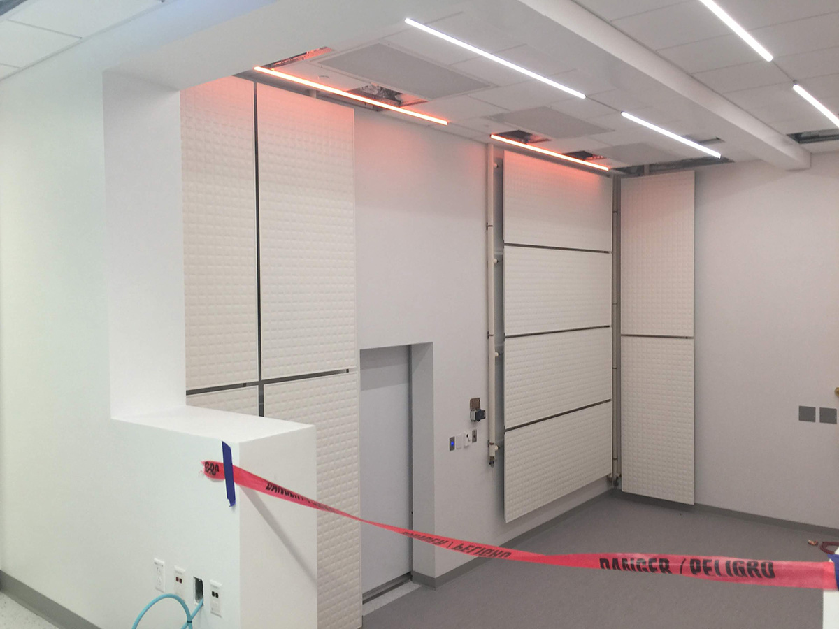
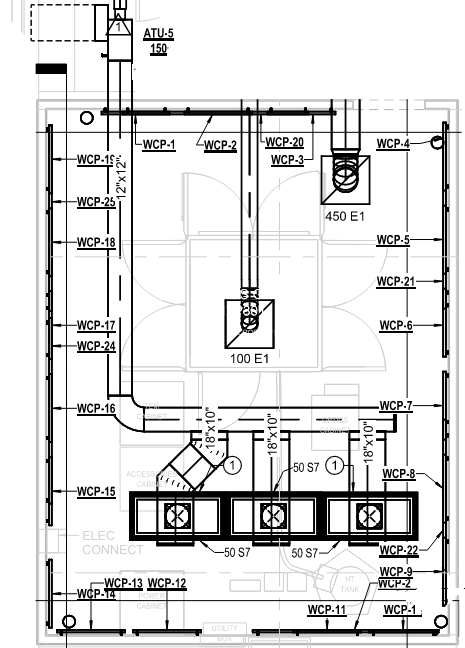
However, because the space was limited and being renovated, the room’s layout made low-level air supply unfeasible. To achieve the required ventilation for pressurization and low-velocity distribution, three two-inch by four-inch high-efficiency particulate air (HEPA) diffusers with 51% free area, each delivering 50 cfm, were installed. This configuration resulted in a discharge velocity of approximately 2.45 in/s, while diffuser locations were strategically decentralized and positioned along the room perimeter to maintain airflow uniformity and minimize disruption.

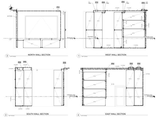
A key thermal management challenge within the microscope room involved rejecting the significant heat load generated by the cryo-EM system and associated auxiliary equipment. Traditional cooling with low-velocity diffusers through house air was not viable, as this approach would have required additional ceiling grid space that was not available. Instead, passive cooling panels were installed along the walls. This solution effectively managed equipment-generated heat while eliminating excess air movement and noise, which were both critical to maintaining the microscope’s imaging performance.
Air quality and filtration
Clean air is essential to prevent dust and particulates from contaminating sensitive optical components. Systems included HEPA or ultra-low particulate air filtration (99.99%+ efficiency) at terminal diffusers. Positive pressure control in the microscope room prevented infiltration of unfiltered air.
Electromagnetic and acoustic interference mitigation
HVAC and other building components can generate electromagnetic fields and noise that interfere with the microscope’s imaging system. The equipment must be in a part of the building that is isolated from sources of fluctuating magnetic fields, such as those generated by elevators, transformers or motors.
System zoning and redundancy
Microscope rooms, prep rooms and control areas often require separate zones with different environmental conditions. Zoned HVAC systems with independent controls to allow adjustments of each area to its specific needs.
Redundancy (N+1 design) in critical systems (chillers, AHUs and humidifiers) ensures reliability for continuous cryo-EM operations. The existing building’s space constraints limited certain systems that could be provided with redundancy, though chilled water redundancy in the plant and emergency power were available.
Monitoring and control
An integrated building management systemis crucial for real-time oversight. This included high-accuracy sensors to monitor temperature, oxygen levels, humidity and air pressure. Alarms and historical logging allow facility staff to respond quickly to deviations.
Designing the anteroom
An anteroom outside of a cryo-electron microscopy room acts as a buffer zone, minimizing rapid fluctuations in temperature, pressure and humidity from outside when doors are open. This protects the microscope’s high-resolution imaging by maintaining thermal stability.
The room also maintains cleanliness and particulate control by allowing personnel to don and doff personal protective equipment outside the microscope room. It also provides security and access control to limit and monitor who enters the lab space.
In summary, the mechanical HVAC system for a cryo-EM facility is a highly specialized, engineered environment that supports the microscope’s physical and analytical performance. It must be tightly integrated with architectural, structural, electrical and lab design systems to ensure long-term stability, reliability and scientific fidelity.
Maintaining a highly sophisticated piece of equipment and its associated HVAC systems requires that the owner’s operators and maintenance personnel understand the equipment and the operational nuances of the HVAC serving it to continue future successes in cutting-edge drug discovery.