A co-location facility is explained, piece by piece.

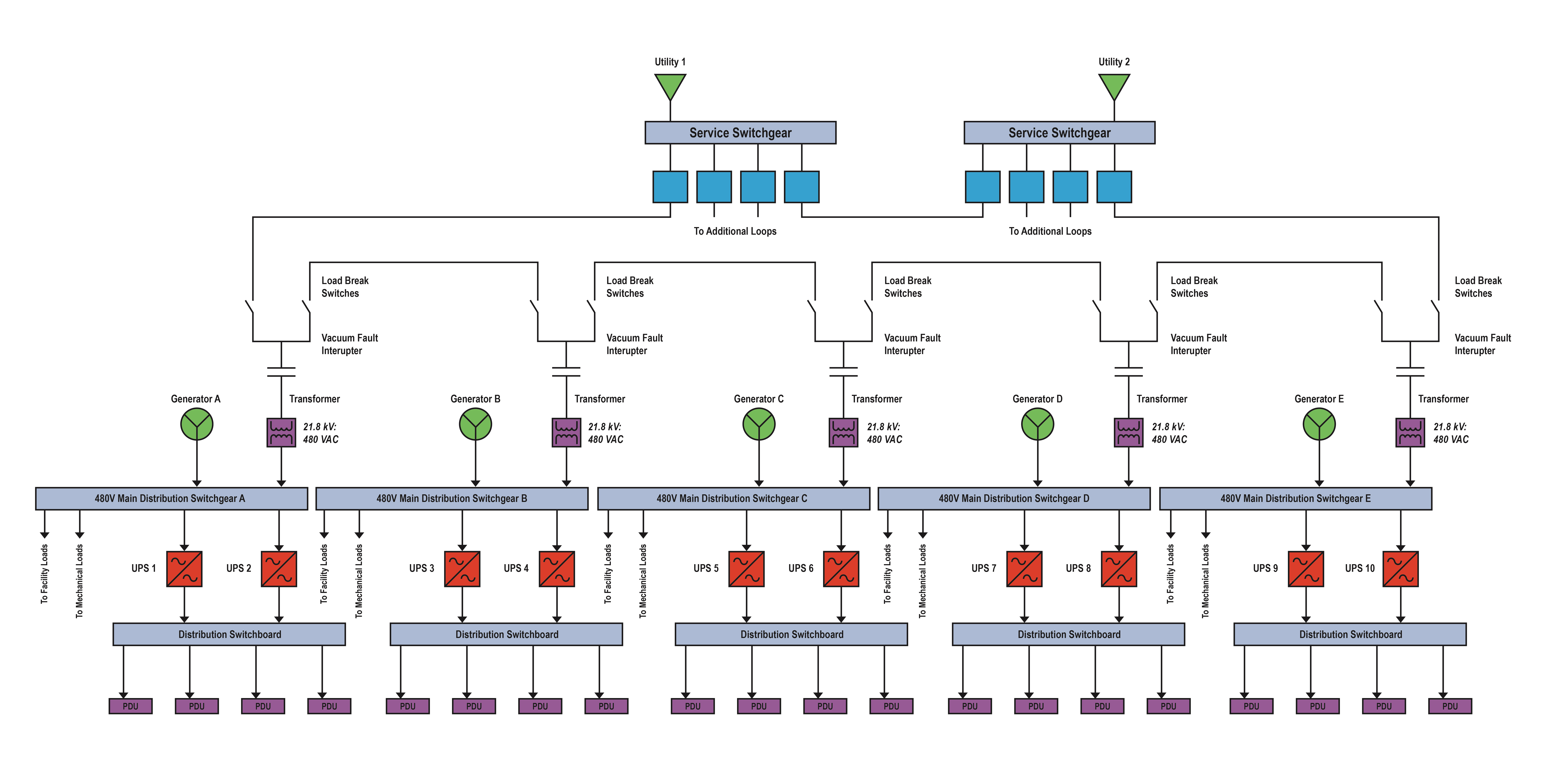
The case study highlighted in Figure 6 is a combination of several systems and has been modified based largely on the preferences of the operational personnel. This is commonplace; it is rare that any data center fits the cookie-cutter example of any topology. Co-location owners have years of operational experience and that experience drives continuous refinement. Due to nondisclosure agreements, some details in Figure 6 have been modified or deleted to respect client confidentiality.
Service–level agreement (SLA): Contents of the SLA are confidential, but concurrent maintainability is required.
IT load: The facility is designed to support 20 MW of peak information technology (IT) load. Note that a single line to support a 20-MW IT load is too large to publish here, so the topology shown in Figure 6 is repeated as necessary to support a full 20 MW. The IT load for the entire co-location is dual-corded at 415/240 Vac. Dual-corded loads allow for the elimination of upstream static transfer switches (STS) and make ensuring a concurrently maintainable system easier to accomplish.
Safety: To address the arc flash issues on the secondary side of the transformers, vacuum fault interrupters were added to the primary side of the transformer, in addition to current transformers on the primary and secondary sides. This allowed for differential protection to be added to the transformer. Additionally, infrared (IR) windows were added to the transformer secondary connections and the 480 V main distribution switchgear to avoid exposure during IR scans.
Site development: Because a utility-owned substation was already onsite, the utility provided two feeders from their substation. Additional positions are available for future expansion but are not required for co-location.
Medium-voltage equipment: The co-location is served by dual 21.8 kV services provided by the utility, feeding dual gas-insulated switchgear (GIS). GIS was selected due to limited site space and the ability to fit it in prefabricated electrical enclosures that are assembled then shipped directly to the site. GIS sections are connected with tie breakers, and each co-location area is fed by an A/B loop system. Load-break air switches were used to segment the loop. Air break switches have acceptable performance at this voltage level, and the addition of the tie breaker reduced the number of load break operations performed by the switches. As noted previously, current transformers and vacuum fault interrupters were added to the primary of each transformer. The 21.8 kV 480 Vac transformers were less flammable, liquid-filled transformers and are provided with KNAN/KNAF ratings.
Standby power: Standby power is provided by dedicated 480 Vac standby-rated diesel generators. The kilowatt rating of the generators was selected to match the KNAN rating of the liquid-filled transformers. Each generator is provided with 12 hours of fuel storage. The UPS are sized to approximately two-thirds of the KNAN rating of the transformers because approximately two-thirds of the load for the co-location is dedicated to the IT load, with the other one-third dedicated to mechanical and facility loads.
PDU: PDUs are 600 kVA and transform from 480 Vac to 415/240 Vac. K-4-rated transformers were included in the PDUs.
Metering: Revenue-grade metering was included at the utility service points, 480 V main distribution switchgear, separate metering for the mechanical and house loads, UPS input and output sections, and PDU output breakers. The metering at the 480 V main distribution switchgear includes current transformer inputs from both the utility and generator sources. Metering must be included down to the PDU output breakers because, in a distributed redundant system, each PDU may feed multiple rows. Metering is not provided at separate mechanical or house loads, or across each transformer. Additional metering will be added at the branch-circuit level later based on specific customer requirements.
Redundancy: Redundancy requirements were specified in the SLA as concurrently maintainable. The system was designed as a distributed redundant system with no STS. Each IT load is fed from two PDUs, with each PDU fed from a different transformer/generator pair. This configuration provides for a simple one-line, but it does require significant load management below the PDUs at the rack level.


