Since first opening its doors in 1944, the University of California at Santa Barbara has grown into a world-renowned research institute. To keep this dynamic university at the forefront, a major capital building program is underway to give researchers the high-tech facilities they need. Naturally, this rapid expansion has brought with it the need to upgrade electrical delivery.
Since first opening its doors in 1944, the University of California at Santa Barbara has grown into a world-renowned research institute. To keep this dynamic university at the forefront, a major capital building program is underway to give researchers the high-tech facilities they need. Naturally, this rapid expansion has brought with it the need to upgrade electrical delivery.
To date, the campus was powered by a 16,000-volt system owned and operated by Southern California Edison (SCE), and a 4,160-volt system owned and operated by the university. Due to aged cable and components, the campus suffered numerous unplanned outages. Making matters worse was that outage length was exacerbated by a lack of redundancy and unavailability of replacement components. As such, the system is being replaced by a new modular infrastructure that will take advantage of emerging automation technology to guarentee a significantly higher level of reliability.
Getting the ball rolling
Back in 2001, UCSB developed a campus electrical distribution master plan in which the university would become owner and operator of the system. The plan standardized on a 12,470-volt, three-phase system where incoming utility power would remain at 66,000 volts, meaning UCSB would have to install its own substation and completely replace the campus’ underground cable system with new 15,000-volt conductors. This required detailed planning and work procedures between UCSB and SCE.
Furthermore, primary transformers for all buildings needed to be replaced to accept the new service. During this transition, SCE was given special consideration due to jurisdictional and ownership issues, and in many cases, temporary generators had to be set up while the old equipment was changed out.
In addition to the fundamental distribution design of transformers, switchgear and cable, the master plan included the use of a high-reliability distribution system (HRDS) that distributed power to individual building service transformers. Rather than offering simple switching and standard building feeder protection, these HRDS switches, consisting of 15,000-volt class-SF6 gas-insulated fault interrupters, are capable of automatically sensing conductor failures within the campus loops and isolating faulted cable sections with virtually no impact on building loads. The status of each HRDS switch throughout the campus and the main incoming service switchgear are monitored via a supervisory control and data acquisition (SCADA) system from a central facility-management location.
Out with the old
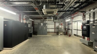
For funding reasons, the new distribution system was divided into three phases starting in the fall of 2002 with the installation of a new 20-MVA, 66-12.47-kV transformer in the same yard as the SCE 16-kV service transformer and breaker rack. Another rack, located on the 12.47-kV transformer side, holds the utility-provided CTs and PTs used for revenue metering. Three sets of 15-kV, 500-kCMIL conductors run underground to the university’s new switchgear building. This facility contains a 48-ft. by 24-ft. underground cable vault and the 15-kV indoor-vacuum circuit-breaker metal-clad switchgear. The switchgear utilizes a main-tie-main configuration with eight feeder breaker position provisions for two additional sections for future cogeneration system connection.
As far as the feeder cable circuits are concerned, they drop from the breakers into the vault and are distributed through UCSB’s extensive conduit and manhole system. Three manholes were added as part of Phase 1 and 12 more are planned for the remaining two phases; there are more than 110 utility manholes on campus. Some 6,000 ft. of new ductbanks and 42,000 ft. of conduit will also be added. In most cases, the new underground loop circuit ductbanks contain six 5-in. PVC conduits for the feeder cables and two 2-in. PVC conduits for the fiber-optic relay communication cables. Phase 1 installed the first 12.47-kV feeder loop, labeled “Research North,” which consists of nine 15.5-kV pad-mounted fault interrupter switches.
Innovative and automated protection
OK, so much for the skeleton of the new system. The real highlight of the new infrastructure is its closed-loop primary-voltage distribution automation system, where switchgear and relays communicate through a multiplexed fiber-optic network (see diagram above).
For additional reliability the system also uses relays and fault-interrupting switchgear to eliminate feeder-cable outages. Meanwhile, the primary network is protected by automatic switchgear.
The switchgear units themselves consist of two 6,000-amp feeder ways and multiple 200-amp branch-line ways—each with vacuum fault interrupters. These interrupters are housed in a sealed stainless-steel tank insulated with SF6 gas. Each switchgear way also has an integrated three-position disconnect and grounding switch in series with the vacuum interrupter.
A large viewing window for each way enables one to easily determine the proper switch position for establishing a visible open gap and grounding of the cables for maintenance operations without any need to open separable elbow connectors on the 12.47-kV system.
Each 600-amp way is trip-controlled by a dedicated relay. The devices are stored in low-voltage cabinets mounted at the end of each switchgear. Battery backup for up to four hours is provided within each cabinet for the relays and fiber-optic transceiver. The 200-amp branch-line ways are protected by overcurrent controls—a microprocessor-based relay powered from the fault current—therefore requiring no batteries or external power.
The switchgear relays on the main feeders provide both permissive overreaching transfer trip (POTT) and directional comparison blocking (DCB) protection to the feeder circuits. This combination provides speed of isolation and redundancy of protection. Before the segment is isolated, the POTT requires the directional overcurrent relays on each end of a cable segment to agree there is a fault between them.
The DCB is the backup scheme and is also active at all times. It is slower than the POTT and is the only scheme functional during open-loop conditions of the circuit. The DCB relays are aligned to trip when they see a forward fault and will do so unless they receive a block signal from their partner relay at the other end of the cable. Both POTT and DCB schemes use the fiber-optic multiplexer system for communication.
The overcurrent control that protects the branch-line circuits from each switchgear is a self-contained relay that acts as a non-directional resettable fuse. It is powered from CTs within the switchgear tank, and is mounted within the switchgear enclosure on the side of the vacuum fault interrupter’s SF6 tank. Each overcurrent control can control two branch-line fault interrupter ways.
Never too much redundancy
Backup protection, in the form of non-directional overcurrent elements programmed in the substation feeder relays, is also provided. These backups coordinate with primary communications protection, branch-line protection and source transformer fuses to allow faults to be cleared even in the event of a complete communications system outage. Furthermore, the relays serve the function of a remote terminal unit at each switchgear by sending valuable information to facilities-monitoring personnel through the SCADA system. Status, control and alarms are provided for each 600-amp way of the switchgear units. Alarms for battery condition, loss of AC power control, loss of communications or high bit-error rate, relay malfunction, status of the local/remote switch, status of low SF6 gas pressure indicator and status of the branch-line fault interrupters are also monitored. The relays provide analog information, including amps, volts, watts and VARs scanned at approximately 4-second intervals. Remote monitoring of the system data is provided to a facilities management center. In addition, information for up to 16 events, stored in each relay, is available by on-site downloads. This information includes distance to faults, targets, amps and oscillography data.
Status, alarms and analog data are then brought back to a substation interface computer in the switchgear building. Interface software—Substation Explorer from Subnet Solutions—provides a graphical user interface at the substation for alarm annunciation, monitoring of power flow and interface to the facilities-management center SCADA system. Graphical views include an overall system one-line diagram and detailed views, down to individual switchgear, to quickly determine the status of any component throughout the distribution system. An automatic dial-out e-mail pager feature of the interface software alerts system operating personnel to critical alarms, assuring prompt response to any evolving system conditions.
The fiber-optic communication system moves the information between switchgear locations less than two milliseconds, that is, a 1/8-cycle delay. Reliable high-speed communication is critical to supporting the 0.1 sec./6 cycles or less total clearing time provided by the primary network protection system. The same fiber-optic system also carries the SCADA information back to the substation interface computer.
To further promote reliability, the fiber system uses a redundant ring topology. This system allows for the immediate re-routing of information to the alternate direction around the loop in the event of a fiber break, dig-in or failed multiplexer. The fiber system can reconfigure from loop to radial operation in 4 milliseconds, or 1/4-cycle, with no loss of data. In fact, it’s so quick that the relays may not even detect the break. This assures the integrity of this critical portion of the distribution system.
Looking ahead
Upon completion of Phase 3, UCSB will be totally self-reliant with its own campus-wide electrical distribution system. With ownership and the new multi-loop distribution system configuration, system reliability and operational flexibility will be greatly improved. A loop feeder fault will be quickly isolated by the HRDS design, and no effect on building power is expected. A failure on a branch-line building circuit will isolate the building feed only and will have no impact on other buildings. Preventative maintenance is enhanced by the multi-point HRDS condition alarms, which are monitored and recorded for all major system devices in the HMI interface located in the main switchgear building. Alarm messages are remotely transmitted to facilities personnel by Ethernet connection and dial-up pagers.
Also, portions of the loop feeders can be opened for maintenance or addition of a new selector switch without affecting building services. All conductors are fire-taped in manholes to prevent collateral cable damage due to catastrophic failure on a separate circuit. At the front end, the two 12-MVA substation transformers provide redundancy, as one will carry the total university load using its fan ratings.
With the common distribution 12.47-kV voltage rating, all switchgear, cables and building primary components are consistent, lessening confusion of multiple system voltages for maintenance personnel. In addition, spare parts inventory is reduced for items such as fuses, conductors and switchgear components.
The electrical distribution system now operates with a microprocessor-based silent sentinel watching over its operation. With its state-of-the-art controls and flexible configuration, the distribution will provide reliable electrical service for UCSB students, professors and staff for decades.
Transformer Troubles
At the age of 61, the University of California at Santa Barbara is relatively young, but has already become a research powerhouse and needs a 21st Century power system. But changing out an existing electrical infrastructure while the university continued to operate was no easy task.
A big portion of phase 1 work included building-transformer replacements from 4,160-volt and 16-kV to 12.47-kV primaries in 11 buildings. With the primary voltage increase, existing equipment locations violated required working and access clearances.
For some buildings, indoor transformers were replaced with outdoor pad-mounted types and secondary feeders were run underground to the existing indoor main circuit breaker and switchboard.
Where 12.47-kV primary transformers could be installed indoors, secondary 480/277- or 208/120-volt secondary connections were made to existing switchboards by cable or bus, whichever method was best suited to the application.
Power for the Future
Though many secondary switchboards have outlived their service expectancy, Phase 1 did not allow for their replacement. Consequently, internal building utility upgrades are planned for the future. Phase 2 will continue conversions from 4,160- and 16,000-volt primary transformers to 12.47 kV. Two more 12.47-kV loops will be installed with eight interrupter switches and 5,000 ft. of ductbank. Furthermore, 10 additonal manholes will be installed with 85,000 ft. of 15-kV conductor. Separable type “T” body connections are being used not only to accommodate cable pull lengths, but also to serve as temporary loop configurations in support of the phased installation. Phase 3 will involve the installation of a second 12/16/20-MVA, 66-12.47-kV substation transformer and its connection to the main service switchgear’s second main circuit breaker. The campus’ fourth 12.47-kV loop will be installed, in conjunction with completion of building service transformer conversions to 12.47 kV, and removal of the university-owned 4,160-volt substation and all associated feeders.