Aquifers are an increasingly important decarbonization strategy. Understand how to take direct, practical steps to integrate aquifer-based systems into their building designs, promoting sustainable and energy-efficient solutions.

Learning objectives
- Define what an aquifer is and identify key benefits of aquifers in heating and cooling buildings, especially in terms of stable underground temperatures.
- Recognize the historical context and early innovations involving aquifer-based thermal systems.
- Analyze how geology and clean energy principles are being combined in modern ATES designs.
Aquifer insights
- In recent years, these aquifers have emerged as unexpected allies in the race toward zero-carbon buildings and climate-resilient cities.
- Understanding the relationship between Darcy’s Law and its impact on the ATES system is crucial for every engineer’s comprehension.
As engineers, our mission isn’t just to design systems, it’s to reimagine how those systems interact with the world around us. As the science of building climate control evolves rapidly, the path to a sustainable, carbon-free future requires that we expand our knowledge and rethink our choices. This is why we must recognize the hidden power of using underground aquifers as thermal storage systems to efficiently heat and cool buildings.
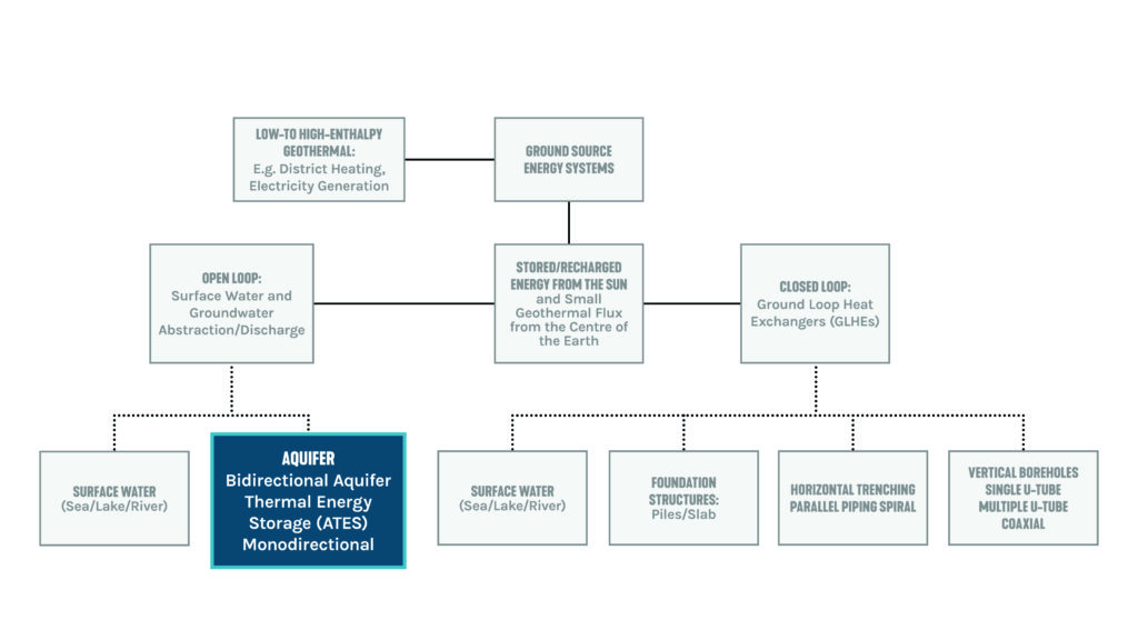
Aquifers have quietly supported agriculture, ecosystems and human development for centuries, operating beneath the surface as natural underground reservoirs. Though often overlooked, they’ve played a vital role in sustaining life and shaping our environment. Figure 1 illustrates various system applications for all types of ground source systems. The first ATES modelling research was conducted by Kazman and Rabimov in the early 1970s, and several sources indicate that this technology was being developed in Shanghai, China, as early as the 1960s.
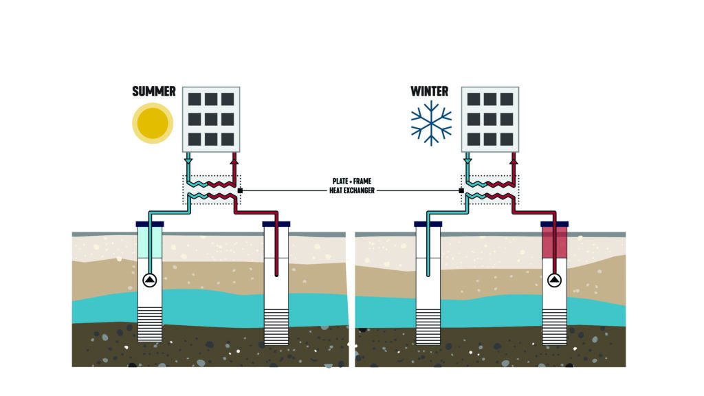
In recent years, these aquifers have emerged as unexpected allies in the race toward zero-carbon buildings and climate-resilient cities. By leveraging their unique thermal properties, engineers are designing systems that use aquifers not only to store water but to regulate temperatures in the built environment, offering heating in winter and cooling in the summer, as shown in Figure 2.
The idea is simple but genius: aquifers maintain a stable temperature year-round, making them perfect for aquifer thermal energy storage (ATES) systems. In summer, excess heat is pumped underground; in winter, that stored warmth is drawn back up to heat buildings. It’s like nature’s own energy bank, sitting quietly beneath the surface. To achieve the climate change mitigation targets, increasing attention has to be paid to the decarbonization of the thermal energy sector.
ATES can be mistaken for ground source heat pumps (GSHP) because they are considered open-loop piping systems with water wells. The primary difference between an ATES system and a GSHP lies in how they utilize the earth’s thermal energy. An ATES system stores thermal energy in an aquifer, while a GSHP extracts heat directly from the ground.
Who is involved?
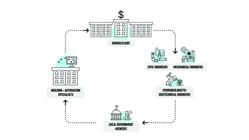
The installation of an ATES system is a multidisciplinary effort involving several key stakeholders, as shown in Figure 3. Hydrogeologists and geotechnical engineers play a crucial role in evaluating subsurface conditions and aquifer suitability, thereby laying the groundwork for effective system design. Mechanical engineers create building design energy models to validate the adequate annual capacity of the system. They often collaborate with civil engineers to develop the infrastructure, including wells, heat exchangers and distribution networks. Environmental consultants ensure the project complies with regulatory standards and assess its ecological impact. Project developers and energy planners coordinate logistics, budgeting and integration with existing energy systems to ensure seamless operation. Local government agencies play a critical role in permitting and regulatory oversight, while drilling contractors and construction teams handle the physical installation. Finally, system integrators and automation specialists ensure the ATES system operates efficiently when the building is functional.
Utilizing Darcy’s Law in underground aquifers for heating and cooling
In 1856, Henry Philibert Gaspard Darcy, in a report on the construction of the Dijon, France, municipal water system, published a relationship for the flow rate of water in sand filters. He developed the Darcy Law formula, which plays a fundamental role in understanding how underground aquifers can be used for thermal energy storage. It describes the movement of water through porous materials, such as the soil and rock layers that make up an aquifer.
According to this principle, the rate at which water flows, which is known as discharge, is directly proportional to both the hydraulic gradient (the change in water pressure over a given distance) and the hydraulic conductivity (a measure of how easily water can move through the material). This relationship is critical when designing systems like ATES, as it helps engineers predict how water will behave underground.
The Darcy formula is as follows;
Q = kiA
Where:
Q is the discharge (volume of water flowing per unit time)
K is the hydraulic conductivity (a property of the aquifer material)
I is the hydraulic gradient (change in water pressure over distance)
A is the cross-sectional area of flow
Understanding the relationship between Darcy’s Law and its impact on the ATES system is crucial for every engineer’s comprehension.
- Groundwater flow and heat transfer: ATES systems involve extracting and injecting groundwater to store and retrieve thermal energy. Darcy’s Law is fundamental to describing this groundwater flow within the aquifer. The flow process in the reservoir conforms to Darcy’s law and follows the mass conservation equation.
- Aquifer characterization: Darcy’s Law helps characterize the hydraulic conductivity of the aquifer, which are key properties influencing groundwater movement and, consequently, the transport of stored heat.
- Thermal transport: The rate and direction of groundwater flow, governed by Darcy’s Law, directly impact the advective transport of heat within the aquifer.
- System design and optimization: Understanding groundwater flow using Darcy’s Law is crucial for designing ATES systems, including well placement, pumping rates and predicting the movement of thermal plumes within the aquifer.
- Evaluating efficiency and performance: Darcy’s Law, through its connection to groundwater flow, is used in modeling and assessing the efficiency and performance of ATES systems, helping to minimize thermal losses and maximize energy recovery.
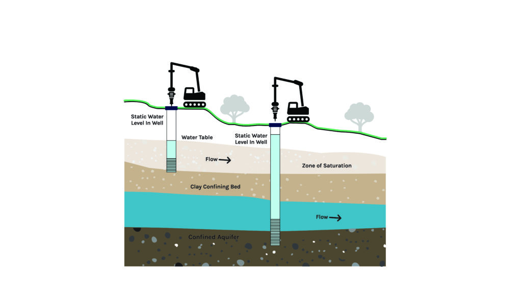
Aquifers can be characterized in several ways, but two broad categories are confined (sometimes referred to as artesian aquifers) and unconfined (sometimes referred to as water table aquifers). As shown in Figure 4, the volume of water flowing per unit of time is influenced by the hydraulic gradient, which is related to pressure. It is important to note that increased pressure on the well influences the energy storage capability of the system.
Single-well closed-loop dipole systems
Engineers include ATES as one part of a wider set of pump-and-reinject techniques in aquifer-based geothermal systems. ATES delivers strong benefits in certain situations, but it doesn’t suit every aquifer or every application. Some formations can’t support it, and other methods may perform better in different contexts. That’s why experts continue to push the boundaries of geothermal design.
A contractor in Minnesota has developed a closed-loop dipole configuration for aquifer-based geothermal systems. This approach uses a single well equipped with a downhole heat exchanger positioned within the aquifer. Unlike open-loop systems and groundwater pump-and-reinject designs, the closed-loop dipole system facilitates thermal exchange directly within the aquifer without extracting groundwater to the surface.
Maintaining thermal exchange below ground helps reduce operational and regulatory challenges. The system limits geochemical risks, including fouling, scaling and biofilm development by avoiding oxygen contact, pressure variation and intermixing of distinct groundwater layers. These design characteristics are especially suitable for stratified aquifers, where lateral flow patterns support efficient heat dispersion.
In contrast to bidirectional ATES systems, it eliminates the need for surface-level infrastructure such as heat exchangers, trenching, and reinjection systems. This makes the design useful for applications with space constraints, such as phased urban development.
Overall, single-well dipole systems provide a method for utilizing the thermal properties of groundwater while maintaining aquifer structure. This design can simplify implementation processes in geothermal energy planning.
Design factors in aquifers
Climate: It’s essential to leverage the relatively stable temperature of the earth beneath the surface, which averages around 55°F across the U.S. year-round; slightly cooler in northern regions and warmer in southern regions. Weather differences play a key role in assessing the viability of an ATES system. Areas with pronounced seasonal changes enhance system performance by offering “free” thermal energy that can be stored and reused.
Energy storage: The ATES system should be engineered to be balanced; that is, to store and use equal amounts of heat and cool on average over each annual cycle. A balanced system is less likely to induce long-term temperature changes in the aquifer or experience thermal interference of the warm and cool groundwater plumes in the aquifer, leading to a reduction of energy storage efficiency.
Load calculations: Preliminary load calculations by the design engineer can help determine the building’s heating and cooling demands, guiding the required bore piping length and depth for proper system installation.
Site considerations: The availability of land at the building or campus location is a key factor when selecting this system, especially where space is limited. Unlike the vertical/horizontal closed-loop geothermal design, which requires a higher number of boreholes spaced farther apart, the ATES system uses significantly fewer boreholes. Typical borehole depths range from 200 to 2000 feet, compared to geothermal systems that typically reach depths of 70 to 500 feet.
Training and education: The training program encompasses both commercial and residential applications, making it valuable for installers, contractors, architects, engineers and anyone seeking to acquire practical knowledge of advanced heat pump technologies.
Codes, regulations and ordinances: Unlike a traditional open-loop GWHP, the closed-loop water being directed into the well is potable and includes only permitted chemical additives and concentrations. In the unlikely event of a leak, the impact on the aquifer would be negligible, which tends to reassure regulatory stakeholders. Typically, the primary permitting requirement for an ATES system will be an underground injection control (UIC) registration.
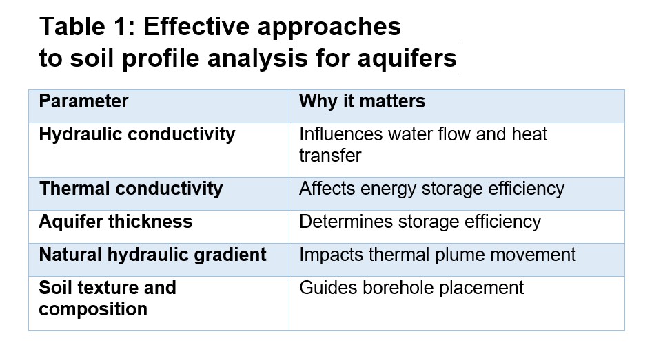
Soil profile analysis: Performing a soil profile analysis is a key component in the design of an ATES system. It provides insight into subsurface characteristics that influence thermal efficiency, groundwater flow dynamics, and the overall feasibility and durability of the system. Table 1 outlines an effective approach.
Before moving forward with the design of an ATES system, it’s helpful to complete a soil profile analysis, including water flow testing. This process provides valuable insights that can guide the decision-making process. Ideally, this analysis should be conducted early in the project to help ensure that the design is both feasible and well-informed from the start.
Associated equipment
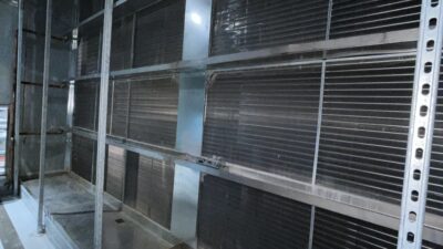
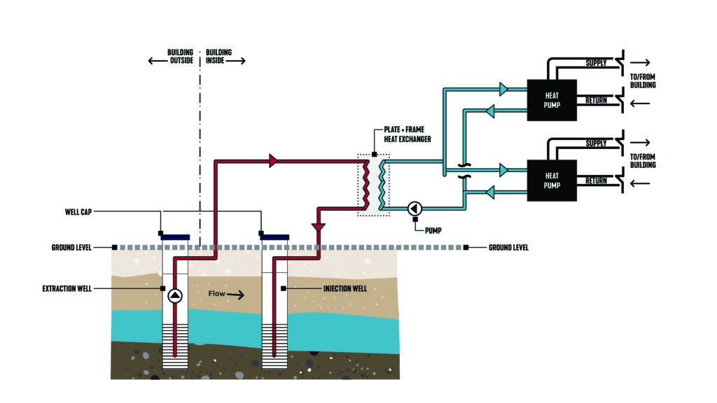
The ATES system connects to the building through a heat exchanger, typically installed indoors, that facilitates the transfer of temperature to the building’s piping loop, as shown in Figure 5. While several connection configurations can be explored when designing the building side, this article focuses on a water-to-air heat pump system for illustration purposes.
The temperature differential usually ranges from 10°F to 15°F between the warm side and cool side of the heat exchanger. Other mechanical equipment includes base-mounted pumps, air separators, expansion tanks, valves, VFDs and distribution equipment, which can be water side or air side.
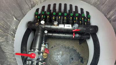
In open-loop systems, a small number of wells (usually one to three) provide groundwater to a plate and frame heat exchanger that interfaces with the building loop. After passing through the heat exchanger, all the groundwater is returned to the ground through a similar number of injection (or reinjection) wells.
When budget permits, capturing heat that is typically rejected or lost during the heating cycle can be redirected to support other building systems, such as generating domestic hot water. This approach efficiently boosts system performance, especially during shoulder seasons, and may also help balance the annual heating and cooling loads.
Compared to conventional technologies, ATES systems achieve energy cost savings between 40% and 70%, and carbon dioxide savings of up to several thousand tons per year. The spatial separation between the injection and production wells helps safeguard groundwater tables during energy exchange, while enabling the system to operate at optimal efficiency.
ATES systems still encounter challenges, including significant initial capital investment and the necessity for large-scale applications to ensure a viable return on investment. Compared to standard open-loop geothermal systems, ATES systems require a more complex pre-investigation and are typically more sensitive to groundwater flow and aquifer heterogeneities. Surface water, and some groundwater, aquifers may contain pollutants or minerals that could contaminate sensitive drinking or irrigation water sources.
Best practices for aquifers
To reduce the risk of injected water short-circuiting back into the production well, the injection well should be positioned downstream from it, following the natural direction of aquifer flow. If the aquifer water is contaminated, coordination with local authorities is initiated to address the issue. During the drilling, development and pump testing phases, water from the aquifer is brought to the surface. If contamination is detected, special treatment may be necessary and can be provided by designated waste management companies that can deal with the cuttings and tailings from borehole drilling. If this becomes a concern, the project team will provide guidance and account for it in the budget on a case-by-case basis.
While it’s relatively rare, drilling obstructions can sometimes cause a borehole to deviate from its intended path — most often in the upper, near-surface layers of the geology at shallow depths. Consult with the installer to determine whether to drill through the obstruction, adjust the borehole’s position slightly or seek further guidance from a geologist or project manager.
A minimum setback of 15 feet from the building should be maintained when placing the well. Additionally, all site utilities—such as water, sewer and electricity — must be properly coordinated to ensure seamless integration into the building systems.