There has been an increased focus on unique cooling solutions for data centers to address the limitations of traditional systems as they house more powerful servers.
Cooling insights
- The evolution of data center cooling from air systems to liquid solutions is because of the need to adapt to high-power processing demands.
- Immersion and direct-to-chip liquid cooling methods offer scalable and efficient alternatives to traditional cooling methods.
Every day, zettabytes (1012 GB, 1 trillion GB or 1021 bytes) of data navigate a global infrastructure of thin glass strands one-tenth the width of a human hair. From medical imaging to streaming movies, data transmission starts by processing data through informational technology (IT) equipment connected to various data center facilities. IT hardware generates heat as it works to process, store and transmit data. For every watt of power distributed to a server, the same amount of heat is generated and needs to be removed. High air temperatures negatively impact the performance of electronic components within data centers. Most electronic devices can operate within an allowable temperature range, but exceeding these limits can lead to reduced efficiency and, in extreme cases, hardware failure. For systems to remain operational, data centers need to implement sophisticated and redundant cooling systems to maintain optimal operating temperatures.
Traditional air conditioning systems have been used for decades to maintain suitable temperatures and prevent equipment from overheating. However, these traditional systems become limited as data centers began to house densely packed powerful servers and their associated processors.

Traditional air-cooling systems
Traditional air-cooling systems feature a raised access floor system with cold air generated by a computer room air handler (CRAH) or a computer room air conditioner (CRAC) unit. CRAC and CRAH units contribute to precision cooling, humidity control and overall efficiency of data centers by ensuring IT equipment operates within specified environmental parameters. CRAC units employ a refrigeration cycle to cool the air, while CRAH units use chilled water hydronic systems. Both units distribute cooled air through raised floors or overhead ducts, contributing to even airflow and temperature distribution.
CRAC and CRAH units remain popular solutions due to cost, ease of installation, flexibility to scale quantity of units and simplicity of control. While they are effective for many data center applications, there has recently been an increase in alternative cooling methods and derivatives to the CRAC and CRAH units for better efficiency and sustainability. These derivatives have advanced in capability from the need to handle increasing IT equipment heat loads and the substantial scale increases of today’s computing facilities.

In-row cooling units are cooling systems explicitly designed for data centers to manage and control the temperature within server rows or small spaces. Unlike traditional perimeter-based cooling systems, in-row cooling units are strategically placed between server racks, bringing the cooling source closer to heat-producing IT equipment. This proximity enhances the cooling efficiency and allows for more precise temperature control. When coupled with hot or cold aisle containment, these units enable higher cabinet power densities and efficiency. Through empirical data and modeling, separating hot and cold air with air containment allows higher IT equipment power densities without the fear of increased IT equipment temperatures from hot air re-entrainment.
Air containment and the separation of hot and cold air comes in many forms. The most common is hot and cold aisle containment, which forms a barrier over the aisle with two rows of IT equipment cabinets and doors at the end of each aisle. This alignment prevents hot and cold air from mixing and optimizes overall cooling system efficiency.
Passive chimneys, also known as passive cooling chimneys, are another option to optimize heat dissipation and airflow management while reducing the energy use of mechanical cooling systems.

Employing a chimney requires the IT equipment cabinets to have solid rear doors and to be fully sealed– commonly including:
-
A cabinet with a solid bottom/skirt around the bottom perimeter.
-
Seals around the front IT equipment mounting rails.
-
Blanking panels for any open mounting spaces on the IT equipment mounting rails.
-
Brushes on the top panel openings to minimize air leakage for cable entry and egress.
Rack-based or chimney containment enables the containment of single cabinets without needing the two rows of cabinets to form an aisle. The containment method is typical in enterprise data centers or colocation facilities where a few cabinets might be in a cage. This method can be implemented in new and existing facilities, offering a scalable solution that accommodates changes in cabinet power density or data center layout.
Cloud computing
One of the most impactful computing changes to data center cooling design was the implementation of cloud computing. Cloud computing significantly impacts the data center facility scale, and the supporting power and cooling systems. Cloud data centers are generally five to 10 times larger than traditional enterprise data centers, with a magnitude of around 20 to 80MW of IT load per facility. This “hyper-scaling” of the data centers changed the way data centers were built and cooled. A standard design methodology to scale equipment and systems for these substantial hyperscale facilities uses air-cooled chillers and fan walls for air distribution.

As demand for data and data processing increases, data center facilities continue to expand, amplifying the need for cooling systems to adapt to the scale of these extensive facilities. To increase cooling on a larger scale, expansive facilities require large fan wall systems. These sizable air handlers, containing 12 to 16 fans arranged in a grid, are designed to supply large volumes of air above 80,000 cubic feet per minute (CFM). These units can have limited fan redundancy built into the design to support a fan failure. Depending on facility operation and maintenance procedures, the failed fan could be replaced with a critical spare that limits downtime. Typically situated around the perimeter of the data center’s technical space, these units circulate cooled air throughout the data hall without needing a raised access floor. This method, known as flooding, necessitates air containment to segregate hot and cold air streams. Without such containment, restrictions on IT equipment cabinet densities would arise, requiring a lower supply of air temperature and significantly increased air volume to manage the mixed air conditions within the space.
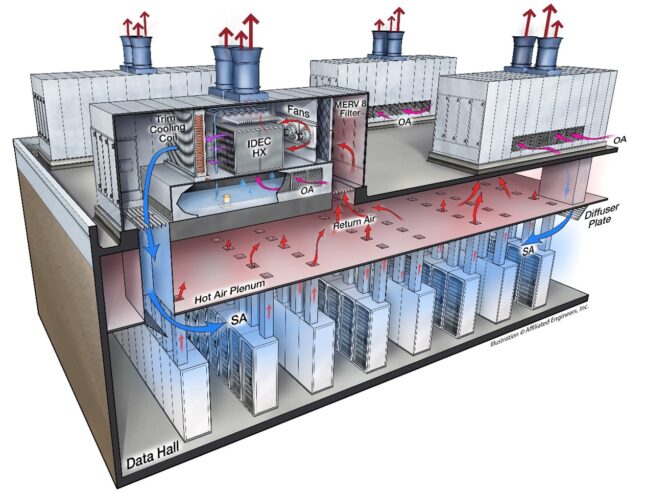
Indirect and direct evaporative cooling
In low humidity climates, large data centers also commonly employ either direct or indirect evaporative cooling to enhance energy efficiency without relying on compressors. The indirect and direct evaporative cooling processes operate similarly to a cooling tower, except they cool air rather than water. Direct evaporative cooling uses outside air or the hot, dry return air from the data center to flow across wetted media in an air handler before being circulated back into the data hall. Since the outside air typically has a low wet bulb temperature, it cools the air in a natural cooling process by evaporating the water. However, the downside of this process is that it directly introduces outside air into a data hall, potentially affecting servers and other devices susceptible to corrosive environments.

The alternative to direct evaporative cooling is indirect evaporative cooling. Indirect evaporative cooling recirculates and returns air across a medium with liquid flowing outside the airstream in the data hall. Manufacturer’s use different heat exchanger materials; some use aluminum plates, while others use a polymer tubes. In both cases, the air does not directly touch the water. While generally less efficient than direct evaporative cooling, the indirect method eliminates the challenges of introducing outside air into the data center and the associated control complexities.
In direct and indirect evaporative cooling processes, it is crucial to maintain water chemistry through chemical treatment systems. Similar to the systems employed for cooling towers, chemical treatment systems must regulate the PH level to minimize calcium buildup on the different media types. Moreover, maintaining proper water chemistry and filtration for reusing discharged water is critical to increase the cycles of concentration and reduce the need for makeup water in the system, especially in geographic locations with concerns about water availability.
For large facilities, bringing outside air directly into the technical space for cooling IT equipment depends on various factors like location, climate and adherence to temperature limits outlined in the most current version of ASHRAE Technical Committee 9.9 Thermal Guidelines. This approach poses many benefits, including simplified system design, reduced components and costs, and lower maintenance and operating expenses. However, there are significant design considerations related to control, geographic location, filtration and the potential risks of air pollution or corrosion to the IT equipment.

IT equipment changes impact cooling methods
Over the last decade, several significant factors have contributed to the increase in data center power density, including the following:
-
Applications like artificial intelligence (AI) and machine learning (ML) with parallel processing utilize high-powered graphics processing units (GPUs).
-
Dense servers have more processors, thereby increasing the server power density.
-
Densifying software applications through virtualization and increasing server power utilization to support running multiple applications on a single server.
-
Increases in computing software utilization.
-
Growing computer chip (processor) power densities.
-
Decreasing processor case temperatures reducing hours of economizing availability.
-
General growth in demand for data and the processing of the data.
As a result of advancements in chip technologies, which allowed multiple virtual servers to operate within a single physical server, power demands continue to rise. Consequently, data centers gradually became more densely packed with IT equipment. Average densities, which hovered around 2.2kW/rack in the mid to late 2000s, have almost quadrupled to approximately 8.5kW/rack, with peak densities reaching about 20kW/rack. This increased density posed challenges for air cooling systems to dissipate the generated heat effectively and efficiently.

New products, like rear door heat exchangers, were introduced to the market to address higher density loads at these cabinet power densities. There are two types of rear door heat exchangers: passive and active. Passive rear doors resemble a cooling coil integrated into the rear door of the IT equipment cabinet. They rely on IT equipment fans to circulate air across the coil. A drawback to this method is that it requires the IT equipment fans to overcome the resistance of the coil. In general, IT equipment manufacturers do not typically design their hardware or associated fans to handle additional resistance beyond the server’s internal components.
Alternatively, active rear door heat exchangers employ fans that draw air from the IT equipment exhaust through the coil, reducing the workload on the server fans. These active systems can measure pressure in the rear of the IT equipment cabinet to alleviate the pressure (resistance) imposed on the server fans.
Within the last decade, the rapid expansion of virtualization of applications has led to most applications being virtualized to their fullest extent and hosted in a cloud environment. This has notably decreased the number of servers required and the footprint needed for computing systems. However, despite these advancements, the growth and demand for computing has outpaced the progress of server virtualization due to the belief that software development has caught up with hardware capabilities.
To meet the increasing demand for computing, cloud applications and storage, data centers must expand in size and number. Today, data center campuses are approaching and exceeding a gigawatt capacity to accommodate a dozen or more buildings, and each building is expected to handle tens to hundreds of megawatts.

In the last three years, significant growth in applications to support ML, AI and large language models has occurred. These applications require a substantial increase in computing power to perform operations and produce results within a reasonable timeframe. To achieve these results, a combination of high-powered general-purpose graphics processing units and other high-powered central processing units (CPUs) are necessary to generate the results within a reasonable timeframe. Commonly, multiple GPUs are positioned in a server or server blade to support the computing. The blades and server chassis are arranged in large clusters to perform these calculations, resembling the traditional high-performance computing (HPC) clusters typical implemented for research computing (supercomputing). Today’s cabinet power densities are growing and ranging from 50-500kW per computing cabinet.
The processors have increased in core count and onboard memory to achieve the desired outcomes. These advancements have substantially boosted the processor power, and chips with a thermal design power (TDP) range from 300 W to 1,000 W are becoming commonplace. It’s anticipated that processor power will continue to rise, and the thought of a 2,000 W processor in the coming years is an expected possibility. A critical factor concerning these dense, power-hungry silicon devices is the need for lower case temperatures to achieve computing performance.
The processor’s integrated heat spreader (case) is the thermal interface point between a heat sink and the processor. As the processor’s TDP increases, many processors are experiencing a need to reduce the case temperature to mitigate against leakage current, causing the processor to consume more power.
Liquid cooling
The focus has shifted from air to liquid cooling, a concept familiar with cooling high-density computing electronics to accommodate the cooling demands of these high-power processes. In 1975, Seymour Cray introduced the Cray-1, one of the first liquid-cooled supercomputers. Although the cooling technology employed in the Cray-1 differs from today’s standard liquid cooling methods, it sets the stage for future adoption and implementation.
Liquid cooling is gaining significant momentum in the data center cooling market for a few reasons, including:
-
The need to cool high-power processors.
-
The ability to cool more high-power processors within a single server.
-
The continued reduction in data center cooling power.
Many liquid cooling options are arriving in the data center cooling market for various applications. Some liquid cooling solutions are better utilized in certain conditions than other alternatives, especially when it comes to the following:
-
Scale of deployment.
-
Concerns around liquid in the data center.
-
Fluid types.
-
Ability to support power densities.
-
Overall cooling approach.
The two main categories for liquid cooling are immersion cooling and direct-to-chip liquid cooling (DLC).
In its simplest form, immersion cooling involves submerging the server, and all its components, into a dielectric, thermally conductive fluid. These fluids usually consist of either a single-phase fluid or a two-phase fluid.

Single-phase fluids do no change state and are in direct contact with the heated components to remove the heat. In general, the fluid is expected to circulate in the tank and across the components to remove the heat.
Two-phase fluids utilize the phase change of a liquid, transitioning from liquid to vapor, to absorb and carry away heat from the elements. This method offers enhanced cooling capabilities, especially in scenarios with high heat flux components. These fluids are non-mechanical refrigerants that don’t require vapor compression cycle. However, consideration needs to be given to the global warming potential of these fluids, as it is higher than the single-phase fluids, but still lower than current mechanical refrigeration refrigerants.
The standard approach to immersion cooling uses a large container, like a tank, to house the liquid and IT equipment. If the immersion system is procured as a package, it is expected to come with controls, pumps, valves, heat exchangers and other telemetry to control the cooling operation. Most tanks are fabricated from painted carbon steel or stainless steel. The tanks will also have mounting locations outside the fluid for the power strips to deliver power to the IT equipment and switches for communication between the IT equipment. It is important to note that not all IT hardware vendor’s equipment will come ready to be placed in a tank of dielectric fluid for cooling.
Further, considerations for implementing this type of system need to include:
-
Facility water temperature delivered to the tank.
-
Lifting apparatus to lift the servers out of the tank.
-
Spill cleanup.
-
Containment for possible leaks.
-
Detection and monitoring for possible leaks.
-
Fluid storage and disposal.
-
Ancillary cooling for the heat rejected from the tank.
-
Fire suppression system.
DLC also comes in single-phase or two-phase options for cooling the equipment. DLC uses cold plates directly in contact with the processor’s case. The cold plate contains the fluid passing through microchannels to reject the energy produced by the processor.
DLC is typically focused only on processors and other high-heat flux components. Unfortunately, this leaves the less energy-intensive heat-generating components to be cooled by air. The computer room cooling system will commonly cool these components, which in turn cools also cools other IT equipment within the space, such as switches and storage hardware.
There are two types of DLC systems:
-
Single-phase DLC: Fluids (deionized water or water treated with bacterial growth inhibitors) remain consistent within the cold plate and fluid network. This fluid circulates through the microchannels within the cold plate and then moves to a heat exchanger to dissipate the heat.
-
Two-phase DLC: There is phase change of a liquid within the cold plate. The fluid enters the cold plate and changes from liquid to vapor through an evaporative process. The vapor is then returned to a heat exchanger, condensing into a liquid.
DLC, in general, has an extensive adoption base and has been implemented in many large-scale data centers and HPC computing systems worldwide.
There are two distinct loops of cooling fluid for immersion and DLC: facility water systems (FWS) and technology cooling systems (TCS). Generally, the TCS loop cools the IT equipment, and the FWS loop takes the heat from the TCS loop through an intermediary device, called a coolant distribution unit, to reject the heat outside the building.

The design of liquid cooling systems introduces new challenges for engineers compared to traditional air-cooling methods described earlier.
During the design process, evaluating the considerations listed below with a perspective adjusted to the characteristics and requirements of liquid cooling systems becomes imperative.
-
System redundancy.
-
Decision on working fluid, single-phase or two-phase.
-
Water temperatures both in the FWS and TCS loop.
-
Fluid flow rate and pressure.
-
Fluid chemistry.
-
Structural infrastructure.
-
Fluid containment.
-
Fluid material compatibility.
-
Fluid connection types and piping material.
-
Ancillary sources of heat rejection.
-
Potential fluid impacts should the fluid leak.
-
Removal of the fluid in the TCS loop.
Although designing heat rejection and FWS loops is typically straightforward, additional opportunities exist to leverage the heat generated from the liquid-cooled systems. While air-cooled systems face limitations due to lower heat density and temperatures, liquid-cooled systems offer potential in these areas. When operating, the ability to capture heat from the computing systems is substantial and can potentially offset the need for other hot water heating sources.
While this seems promising, there are numerous considerations to evaluate when implementing this approach, including:
-
Computing systems availability and operational timelines.
-
Interactions with the overall building systems.
-
Low-temperature hot water system design (110°F-120°F)
-
FWS and TCS water temperatures.
-
Processor operation at elevated water temperatures.
-
System components.
-
Control of the system.
While heat reuse sounds intriguing, a water-side economizer might offer greater efficiency and lower capital and operational costs in certain climates and applications. If the objective is to diminish reliance on carbon sources for heating, reusing the energy captured in the water from computing systems could be a viable option. However, a thorough analysis is necessary to determine how it will be implemented and the overall impacts on the system.
The demand for efficient cooling solutions has shifted from traditional air systems to innovative methods in the dynamic landscape of data centers. The industry is evolving from in-row cooling units optimizing temperature control to immersion and DLC that address high-power processors. Integrating sophisticated cooling systems becomes paramount as data centers grapple with increasing power densities driven by technological advancements. The choice between immersion and DLC brings a nuanced approach to dissipating heat, offering scalability and efficiency. Moreover, considerations for heat reuse underscore the industry’s commitment to sustainability, exploring ways to harness computing-generated heat for environmental benefits. As the data center ecosystem navigates this transformative phase, the interplay between power-hungry technologies and cutting-edge cooling solutions defines the trajectory toward a resilient and sustainable future.