Pump speed has always been a critical factor in assessing fire protection system performance and can now be used as much more of a design consideration
Learning Objectives
- Understand the range of the fire pump performance curve.
- Recognize the effect of pump speed on system pressures.
- Identify options available for controlling pump speed.
Pump speed has always been a critical consideration in assessing centrifugal fire pump operation and the performance of the overall fire protection system being served by the fire pump. Until about 20 years ago, all centrifugal fire pumps were mandated by NFPA 20: Standard for the Installation of Stationary Pumps for Fire Protection to operate at a constant rated speed.
The intended pump was specified by the system designer, and pump performance in terms of flow and pressure at the rated speed was confirmed by the listing organization, marked on the pump’s nameplate (see Figure 1) and verified through acceptance testing.
Since the 2003 edition of NFPA 20, fire pumps operating at speeds less than their rating have been allowed giving the design engineer more options in meeting overall fire protection system performance objectives.

Fire pump performance curve
Centrifugal fire pumps are manufactured to operate at a specified rated speed. For example, a given 750 gallons per minute pump, as represented by the performance curve in Figure 2, will produce a net pressure of 90 pounds per square inch when operating at a speed of 3,550 revolutions per minute.
However, the pressure produced by the pump at that speed will vary depending upon the flow demand of the fire protection system. As the flow through the fire pump increases, in this case to a value greater than 750 gpm, the pump produces less pressure.
Conversely, when the fire protection system’s hydraulic demand is less than the pump’s rated flow, pressures greater than the pump’s rated pressure will be produced. The operating range in Figure 2 applies when the pump operates at its rated speed of 3,550 rpm. If the pump operated at some other speed, the performance curve would be altered.
NFPA 20 sets limits on the pressure ranges that can be produced by the pump. Pump manufacturers produce pumps that fall withing the bounds of this range. Pumps operating at a given speed develop their maximum pressure output when no water is discharged downstream of the fire pump discharge flange i.e., when no water is flowing out of the fire protection system or from a test header valve. This condition is referred to as shut-off, churn or zero flow.
Paragraph 6.2 of NFPA 20 limits maximum churn pressures to 140% of the pump’s rated pressure when the pump operates at its rated speed. Therefore, a fire pump rated at 90 psi cannot develop a churn pressure greater than 126 psi at its rated speed. Churn pressures less than the 140% limit are acceptable and would present pumps with “flatter” performance curves.
The manufacturer’s information specific to the pump in question needs to be ascertained (see Figure 2), as this would indicate the actual churn pressure for the pump as well as the rated flow, pressure and speed. The fire protection system would be exposed to churn-condition pressures on a fairly routine basis — for instance, weekly — depending on the testing frequency required by NFPA 25: Standard for the Inspection, Testing and Maintenance of Water-Based Fire Protection Systems for the specific type of pump driver. Under weekly pump tests, the discharge of water from the pump test header or through a metering device is not required.
The other end of the pump’s operating range is referred to as the overload point. NFPA 20 identifies this as 150% of the rated flow. For the 750-gpm pump in Figure 2, this would be 1,125 gpm. As noted above, when flow through the pump exceeds the rated flow, the pressure produced by the pump drops. NFPA 20 limits the pressure drop to no more than 65% of the pump’s rated pressure.
Therefore, a fire pump rated at 90 psi cannot develop an overload pressure less than 58.5 psi at its rated speed. Overload pressures greater than the 65% limit are acceptable and would also present pumps with “flatter” performance curves. Depending upon the source and characteristics of the water supply, pumps operating near their overload point could create adverse suction conditions.

High discharge pressures and low suction pressures
A key consideration with a fire pump is to assure that when it operates at any point along it permissible range, the pump does not create adverse conditions that could jeopardize overall fire protection system performance. NFPA 20 specifically addresses this concern under churn conditions. Paragraph 4.7.7.1 requires that the net pump churn pressure plus the maximum static suction pressure, adjusted for elevation not exceed the pressure for which system components are rated. Standard system components are typically rated to 175 psi although higher pressure rated components are available.
Consider an example of a 1,000 gpm at 150 psi rated pump when operating at a rated speed of 1,760 rpm. The pump’s purpose is to boost the available water supply with a static pressure of 55 psi and a residual pressure of 40 psi at 1,100 gpm.
At the pump’s churn condition the net pressure produced is around 173 psi. When added to the available water supply, the total combined pressure is about 228 psi, well in excess of the 175-psi rating of standards system components. As noted above, churn conditions would be expected on a routine basis such as when the pump undergoes routine weekly testing.
While it presents the most extreme case, the churn condition is not the only point along the curve at which the pump can produce pressures greater than the rating of the system’s components. Any point along the combined curve in which system pressures exceed a specified limit are of concern. When a sprinkler system first operates, the full hydraulic demand is not simultaneously and immediately called upon. As a result, much higher pressures than the calculated system-demand pressure will be encountered because of this lower flow condition.
Consider an early suppression fast-response system for a warehouse consisting of a 12-sprinkler design area for which the flow and pressure demands are calculated to be 2,160 gpm at 98 psi. When the system first operates, usually only one or two sprinklers activate, not all 12 simultaneously, resulting in much lower initial flow demands. Because of the permitted operating range of the fire pump, pressures much greater than 98 psi will be produced at these lower system-demand flows.
While the pressures produced during initial system operation will be less than those produced during the churn condition, the resulting pressures can be significantly high and need to be contemplated, especially with highly fluctuating water-supply pressures.
Addressing excess pump pressures becomes more straightforward when water is supplied from sources with relatively steady nonfluctuating pressures — for example, from a suction tank. For this type of water supply, the maximum pressure at the pump suction flange is a result of the highest elevation of the water level within the tank. With basic information about the water level in the tank and the pipe arrangement leading to the pump, the maximum suction pressure at the pump suction flange can be readily determined.
Fire pump water supply
Municipal water supplies and very large private-service supply networks can experience wide pressure fluctuations with respect to associated flows within and from the supply network. These fluctuations may be caused by a range of factors, such as seasonal conditions or nonfire protection demands placed on the supply network.
Traditional fire protection practice is to use the water supply data that provides the least amount of flow and pressure. This provides for a conservative assessment to assure that the fire protection system delivers the required discharge when the water supply is at its anticipated lowest condition. However, the high points of the water supply should not be overlooked.
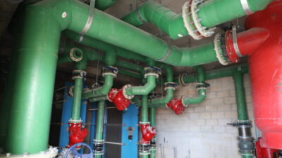
The flow characteristics of water-supply mains and piping networks need to be thoroughly evaluated to determine their potential range of pressure fluctuations. The highest pressures anticipated need to be accounted for during the design and layout of the fire pump installation. When a pump operates, it increases the pressure of the incoming waterflow from the supply as illustrated in Figure 3. The higher the incoming pressure from the water supply, the greater the overall pressure produced.
Recall that NFPA 20 requires the net pump shut-off (churn) pressure plus the maximum static suction pressure from the water supply, adjusted for elevation, not to exceed the pressure rating of system components.
The other end of the pump’s performance curve could also present a cause for concern. When a constant speed pump operates near its overload point, adverse suction conditions could occur depending upon the water supply source. Some water purveyors limit suction pressures to a certain value such as 20 psi. A threshold value is typically set to minimize the occurrence of low pressures in the water mains that could cause undesirable conditions such as groundwater or backflow contamination or in extreme cases a collapse of the main.
Therefore, if the fire protection system demand calls for flows approaching the overload point, the fire pump could cause the suction pressure and pressure in the water supply main, to drop below 20 psi or some other specified threshold value. This situation also needs to be contemplated by the system designer.

Adjusting fire pump speed
Since the 2003 edition, NFPA 20 has allowed for variable speed pumps as an additional option for addressing high discharge pressure and low suction pressure concerns. The concept of variable speed pumps entails a means for controlling pump speed as a design parameter so that discharge and suction pressures can be better regulated to meet overall fire protection system objectives.
This is typically accomplished with supplemental electronic controls and pressure transducers that monitor the discharge pressure and in some cases the suction pressure of the fire pump. The pump speed is modulated down from its rated speed to limit the pump discharge pressure to a preset maximum. Similarly, the pump speed can also be modulated down from its rated speed to limit the pump suction pressure from dropping below a preset minimum. Once the pump reaches it rated speed, the flow-pressure performance follows a traditional fire pump curve.
Three distinct means of providing for variable speed pumps are addressed by NFPA 20. In all cases it is the speed of the pump driver that is adjusted. The speed of an electric motor drive, as illustrated in Figure 3, can be regulated by a specialized type of fire pump controller (reference to paragraph 10.10 of NFPA 20). The controller regulates the speed of the motor by changing the characteristics of the electrical energy sent to the motor.
The speed of a diesel engine drive, as illustrated in Figure 4, is regulated by controls on the engine itself (reference to paragraph 11.2.4.3 of NFPA 20). The engine controls adjust the rate of fuel supply to the engine. The third option is what is defined as a self-regulating variable speed fire pump unit. This is a factory-built integrated fire pump unit consisting of a pump, driver and variable speed control unit configured to maintain set pressures (reference to paragraph 4.8 of NFPA 20).

Regardless of the means of variable speed used, the overall intent is to limit the speed of the fire pump so that pump pressures do not exceed specified values. Referring to the 1,000 gpm at 150 psi pump example, it can be observed that excessive pressures, above 175 psi, are produced by the pump installation for flows below approximately 1,150 gpm. This occurs when the pump operates at its rated speed of 1,760 rpm. With a means of controlling pump speed, the high-end pressures produced by the pump can be capped to a set value, in this case to 175 psi.
Another theoretical example illustrates the application of a variable speed controls. The rated pump speed of 1,760 rpm is reduced for pump flows below approximately 1,200 gpm. Between this point and the churn condition, the pump speed is steadily reduced to approximately 850 rpm. The result is that pump flows ranging from the churn condition to 1,200 gpm will not result in pressures greater than 175 psi.
The modified pump curves developed through the application of speed controls can be applied by design engineers to inform other design decisions. For instance, variable speed drives can be used to increase the available pressure at the anticipated sprinkler demand flow. This in turn could allow for longer branch lines or smaller pipe sizes. The allowance for longer branch lines provides for more flexibility in the system layout that can result in a reduced number or arrangement of cross mains and feed mains.
Another example considers a standpipe system in a tall building. The pump needs to produce pressures that will meet the system demand on all floors of the building including the highest one. Furthermore, the pump is to produce pressures that will overcome the associated pipe friction, fitting and elevation losses up through the system.
Operating pressures at the lower floors will be much greater than the system-demand pressures calculated at the hydraulically most demanding area, which is usually near the top of the building. This presents excessive pressure concerns at lower floors, whether water is flowing from standpipe outlets at the higher floors or at the lower floors. Here again, a variable speed drive arrangement presents an option for limiting excessive pressures at the lower flow demand floors.

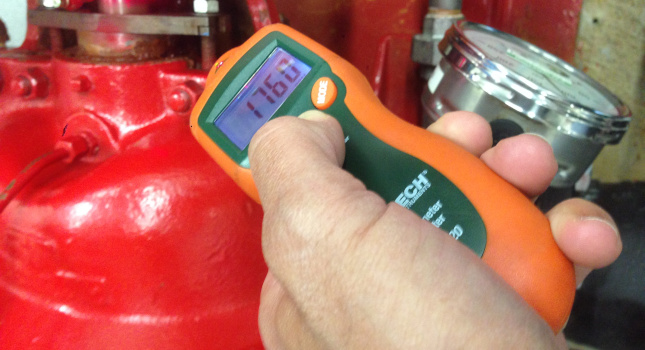
Variable speed pumps present one of several options to the design engineer for addressing high system discharge pressures or low suction water supply pressures. Pumps with flatter performance curves, pressure reducing valves downstream of the fire pump’s discharge isolation valve, break tanks and low-throttle suction valves present possible other alternatives. Regardless of if a constant speed pump or a variable speed pump is used, verification of proper pump speed needs to be obtained during acceptance testing and follow-on routine testing per NFPA 25.
Figure 5 illustrates the use of a tachometer in verifying pump speed during testing. It needs to be appreciated that significantly more test points need to be verified for variable speed pumps. If at any time during its service life the pump operates at a speed other than what was specified by the design engineer, the performance of the fire pump and the overall fire protection system comes into question and requires prudent evaluation and correction.