Chilled water plant optimization strategies can be deployed through traditional programmed sequence of operations
Learning Objectives
- Review codes and standards for efficient operation of chilled water plants.
- Learn simple optimization techniques using standard programmed sequence of operations.
- Understand the efficacy of traditional chilled water plant optimization packages.
The relatively high energy cost of cooling commercial buildings has long caused owners, operators and engineers to seek efficiency improvements leading to energy cost savings. Those improvements have progressed from new pumping strategies (variable-primary flow) to complex optimization techniques, all the way to the incorporation of machine learning algorithms.
As the bar for performance continues to rise, heating, ventilation and air conditioning professionals will need to update their skill sets and even their vocabulary to keep pace with the latest advancements.
Chilled water codes, standards
For buildings taller than two stories in height and/or 25,000 square feet, energy codes typically allow for energy compliance via four different paths:
- ASHRAE Standard 90.1: Energy Standard for Buildings Except Low-Rise Residential Buildings — Prescriptive.
- ASHRAE 90.1 — Performance.
- International Energy Conservation Code — Prescriptive.
- IECC — Performance.
No matter the path selected, the mandatory provisions of the selected code/standard must be followed. The remainder of this section will focus on the mandatory and prescriptive path requirements as defined in ASHRAE Standard 90.1-2019. The optimization related requirements in the latest version of the IECC are similar — a full comparison is beyond the scope of this article.
Note that, while the following requirements will apply to most medium to large projects with a central chilled water plant, exceptions to each requirement exist in both ASHRAE 90.1 and the IECC.
ASHRAE 90.1 Section 6.4.3.10 requires that a direct digital control system be provided and be capable of: “monitoring zone and system demand for fan pressure, pump pressure, heating and cooling and transferring zone and system demand information from zones to air distribution system controllers and from air distribution systems to heating and cooling plant controllers.”
This information transfer provides the chilled water plant with data that can serve as data points or “constraints” in the optimization process. For a central chilled water plant, Section 6.4.3.11 provides requirements for data collection and trending requirements of chiller plant energy use and efficiency.
The prescriptive compliance path of ASHRAE 90.1-2019 (Section 6.5.1) requires the use of an air economizer, fluid economizer or a condenser heat recovery system. Where a fluid economizer is used, the standard requires it be sized for 100% of the expected cooling load with outdoor air temperatures of 50°F dry bulb and 45°F wet bulb and be placed in an integrated position, allowing the heat exchanger to provide partial capacity even when mechanical cooling is still needed to meet the total load. See Figure 1 for a sample chilled water system diagram with the fluid economizer heat exchanger piped in an integrated position.
The prescriptive path (Section 6.5.4.2) requires the use of a variable speed pumping system in which pump speed is modulated to maintain a differential pressure setpoint. In addition, the system must include either differential pressure reset controls or chilled water supply temperature reset controls in which the differential pressure is reset downward or the chilled water supply temperature is reset upward based on chilled water valve positions throughout the system.
These strategies are now commonplace in systems; however, some building operators are not familiar with optimized setpoint sequences that cause setpoints to change automatically. The logic and data driving the sequences is often hidden in the code, making it difficult for the operator to understand why setpoints are changing and which zones are driving it.
Requiring that the controls vendor provide a graphic specific to the reset sequence can help the operator understand the dynamics of the system and reduce instances of optimized setpoint sequences falling victim to user override. At a minimum, the graphic should show the position of all chilled water valves and allow the operator to toggle whether each valve is included in the reset logic.
Chilled water optimization strategies
Chilled water plants designed to satisfy minimum energy code requirements are off to an excellent start, but can still be further improved upon. There are several additional simple strategies that can be incorporated in the design and control of the chilled water plant to improve plant efficiency and performance.
The following strategies were developed and described by Steven Taylor in a June 2012 “ASHRAE Journal” article titled: Optimizing Design and Control of Chilled Water Plants — Part 5: Optimized Control Sequences and assume that variable speed drives are provided for all major equipment. Refer to the source document for additional details and calculation procedures.
Stage chilled water pumps based on chilled water flow ratio (actual flow divided by design flow) as opposed to by pump speed. For example, if the system is designed with two pumps, each sized for 50% of the design flow rate, the staging sequence would stage up from one pump to two pumps when the chilled water flow ratio rises above 47%.
Prioritize chilled water temperature reset over differential pressure reset. Chiller efficiency is primarily a function of the difference between leaving chilled water temperature and leaving condenser water temperature — a metric known as “lift.” Increasing the chilled water supply temperature decreases lift, improving chiller efficiency. It is true that a higher chilled water supply temperature will require the pumps to produce additional flow; however, the energy savings from the chiller typically outweigh the increase in pump energy.
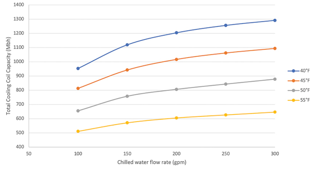
Figure 2 depicts total cooling capacity for a 20,000 cubic feet per minute, eight-row cooling coil for various flow rates and entering chilled water temperatures. It is important to note that chilled water coils are significantly more sensitive to entering chilled water temperature than flow rate.
For this reason, it is vital to size cooling coils serving technical cooling loads or any other loads that experience peak or near-peak design loads frequently throughout the year for a higher-than-design chilled water temperature; otherwise they will prevent the chilled supply temperature from resetting upward
Operate as many towers as possible while ensuring that no tower is receiving less than its minimum allowable flow. The increased surface area will result in higher heat transfer efficiency and lower condenser water supply temperatures. More towers in operation will also allow for lower fan speeds — and thus significantly lower fan energy in accordance with fan affinity laws. Note that cooling towers have a minimum allowable flow rate specified by the manufacturer (typically 40% to 50%) to avoid scale formation. Low-flow accessories such as weir dams can be specified and provided to reduce the minimum allowable flow.
When the fluid economizer is enabled, operate the fans at full speed, when the economizer is disabled, modulate cooling tower fan speed to maintain a temperature setpoint for the condenser water return temperature, or water leaving the chiller. This strategy is atypical and seldomly employed. Traditionally, cooling towers are controlled by resetting the temperature of condenser water entering the chiller (condenser water supply temperature) based on outdoor wet bulb temperature.
However, chiller efficiency is in part a function of refrigerant lift, which is the difference between CWRT and CHWST. Per Taylor’s ASHRAE article, “controlling tower fan speeds based on CWRT and not CWST may help optimize its operation since CWRT in turn determines chiller lift, which is in direct correlation to chiller efficiency.”
Determining optimum control of variable-speed condenser water pumps is challenging because flow reduction reduces pump and tower fan energy, but simultaneously could cause an increase in chiller energy due to higher lift. Because of these offsetting factors, energy savings are small. Additional models have found that variable speed condenser water pumps could increase the overall energy usage of the plant if not optimally controlled.
Understanding chiller optimization
For these reasons, it is recommended by ASHRAE as stated in “The Fundamentals of Design and Control of Central Chilled-Water Plants” to provide constant speed condenser water pumps and vary the cooling tower speed as previously described above. This control sequence remains a highly debated topic in the HVAC industry.
Stage chillers are based on cooling load and lift. Variable speed chillers run most efficiently when the maximum number of chillers are operating at low load. Staging based on chiller load only could cause multiple centrifugal chillers to operate in surge.
Activate the fluid economizer when the chilled water return temperature is greater than the sum of the outdoor wet bulb temperature (OATWB), design approach of the heat exchanger, expected approach of the cooling tower during economizer conditions and a safety factor of 2°F — to ensure that the added fan/pump energy will be offset by the free cooling benefits. Disable the fluid economizer if the device is not reducing the chilled water temperature by at least 1°F.
ΔTCT (°F) — Expected approach of the cooling tower = OATWB (°F) — CWST(°F)
ΔTHX (°F) — Expected approach of the heat exchanger = CWST(°F) — HX leaving chilled water temperature
Enable economizer if: Chilled water return temperature > OATWB + ΔTCT + ΔTHX + 2
These strategies are simple enough to be programmed by the control vendor for a particular application without the need for a separate optimization package. According to computer simulations by Taylor, the energy efficiency of the sequences described above can be within a few percentage points of the theoretical best chilled water plant efficiency as calculated using a constrained optimization approach.
This means that a third-party chilled water plant optimization package will have difficulty providing higher performance than a well-written, programmed and commissioned standard sequence of operations.
Can traditional and cloud optimization solutions add value and further improve system efficiency? The devil is in the details. The optimization strategies produced by Taylor are applicable to many but not all new chilled water plants — and fewer existing chilled water plants. Optimal real-world strategies will diverge from optimal theoretical strategies as equipment ages, coils and tubes foul, dampers fail and as equipment added in renovations is incorrectly integrated into existing central plant reset sequences. While the bar for standard, programmed sequences of operations have been significantly raised in recent years, there is still a place for effective traditional and cloud optimization solutions.
Chilled water control packages
There is no shortage of traditional chilled water plant optimization packages to choose from. A traditional chilled water plant optimization package is a solution provided by a known industry player that exists on a local controller installed in the building to be optimized. A traditional optimization package for a chilled water plant could cost an owner $200,000 or more including installation and commissioning, so implementing a package is not a decision to be made lightly. The various packages have different capabilities and methods of optimization that can be difficult to compare and decipher.
Vendor literature and presentations often make claims regarding potential chilled water plant energy reduction return on investment of five years or less. The word “potential” is of significant importance; this is because behind it, there are a series of assumptions that the vendor may have made (i.e., the baseline that is used to calculate the savings) that may or may not apply to the application at hand.
Assuming an electricity cost of $0.1/kilowatt hour, an installation cost of $200,000 and a five-year ROI, it means that the optimization package will need to save approximately 2 million kWh of electricity over five years. The engineer will need to carefully analyze this and determine if said savings are realistic for a particular application.
Before recommending an optimization package to an owner, it is important for an engineer to have a good understanding of how the package is designed to operate. This can be a difficult task because most vendors of optimization packages do not readily publish their methods and may require the engineer to sign a nondisclosure agreement before divulging details.
Clues can often be found in publicly available patent documentation; however, it is common for inventions to evolve from the specifics described in the patent documentation as the invention is implemented and improved over time — so information in patent documentation should be verified with the vendor. In addition, the engineer will need to work with representatives of the various optimizations to understand what additional controls, instrumentation and equipment are needed to execute the solution and to ensure the optimized chilled water plant control methods are compatible with the new or existing airside system controls.
Consider a popular chilled water plant optimization package. This solution is offered as a complete chilled water plant optimization package that uses patented algorithms. From a hardware perspective, it requires the provision of variable frequency drives on all fan motors (i.e., cooling tower fans), pump motors and chillers. As stated in the associated patent:
[The optimization package] “provides increased efficiency regardless of cooling demand or load by operating chilled water plant components in a synchronous fashion. In one or more embodiments, this occurs by controlling chilled water and condenser water pumping at one or more pumps to maintain a delta T at particular components or points of a chilled water plant. In general, demand flow operates on individual condenser or water pumps to maintain a delta T across a particular component or point of a chilled water plant. For example, primary chilled water pumps may be operated to maintain a delta T across a chiller, secondary chilled water pumps may be operated to maintain a delta T across plant air handlers and condenser water pumps may be operated to maintain a delta T across a condenser.”
There are two verbiage sections used by the inventor that deserve additional consideration:
- Provides increased efficiency: As previously stated, claims about energy savings must be weighed against a baseline. It is not clear from this section how much more efficient this solution will be relative to the latest industry accepted sequences of operation.
- Secondary chilled water pumps may be operated to maintain a delta T across plant air handlers: This verbiage may imply the need to design the chilled water side of the plant in a primary-secondary pumping arrangement. This approach appears to be against the industry trend of using primary only chilled water pumping arrangements. Further, to modulate a set of secondary chilled water pumps to maintain a constant delta T across the coil(s) of air handling units, one will need to ensure that temperature sensors are installed in the associated AHU coil piping and have said sensors monitored by the building automation system.
The analysis is intended to demonstrate that an engineer will need to have a detailed knowledge of how an optimization solution works to evaluate the potential for savings and to properly design or alter a chilled water plant and associated controls system. In many cases, traditional optimization packages are not cost-effective in new systems because the optimization packages are not significantly (if any) more efficient than well designed and executed modern control sequences.
However, they may serve as a cost-effective solution in existing plants that do not have modern control features. In those cases, the cost to hire an engineer to write control sequences; a vendor to program said sequences; a contractor to install additional sensors, valves and VFDs; and a commissioning provider to commission the system may exceed the cost of the optimization package.
More Solutions
This article is the first in a two-part series on central chilled water plant optimization. Part one discusses code–required and other optimization strategies that can be deployed through traditional programmed sequence of operations and the use and efficacy of traditional chilled water optimization packages. Part two discusses the new wave of cloud-based optimization options — from practical system design considerations to make the system cloud-ready to the concepts behind various machine learning algorithms in use.