Safety is a top priority in a building’s electrical system design
Learning objectives
- Understand the National Electrical Code requirements for safe electrical distribution design.
- Learn the circuit protection strategies required for safe electrical system design.
- Review the requirements for electrical equipment working clearances and equipment room design parameters.
The Electrical Safety Foundation International annually publishes data documenting the total electrical injuries and fatalities in the workplace in the United States. The most recent data are through 2017 and provided in the “Workplace Fatalities and Injuries 2003-2017” report.
The good news is that the report indicates that the total fatalities in 2017 is down 11.6% from the year before (total 136 electrical fatalities), however more than half of these fatalities (54%) occurred in the construction industry. Nonfatal electrical injuries, however, are at a 35% increase from 2016, but just 16% of them occurred in the construction industry.
Electrical hazards are present in a wide array of work settings. A properly designed and maintained electrical system will help prevent and reduce injuries and fatalities. The electrical systems design engineer assumes a large responsibility in designing to mitigate these dangers. Electrical safety must be an integral part of system design, which requires an in-depth knowledge of the applicable codes and standards.
Codes and standards
There are many relevant codes and standards for electrical distribution design as it relates to safety. Table 1 highlights the major players and their respective purposes. The most widely known electrical design code is NFPA 70: National Electrical Code. The NEC is the benchmark for safe electrical design, installation and inspection to protect people and property from electrical hazards.
The NEC has been in existence for more than 120 years, with the first document published in 1896. It has been regularly updated throughout the past century; starting in 1953, it has been revised every three years. The frequent updates are intended to help designers stay abreast of the rapidly changing electrical industry. With each new edition, there are enhancements that directly increase electrical safety for the installer, facility manager and end user. Some of the more notable changes over the past two decades that have greatly changed the way we design safe electrical distribution system are outlined in Figure 1.
While it may seem that the NEC and other codes and standards increasingly stringent requirements inherently add cost to the owner and burden on the engineer and installer, the changes are largely focused on enhancing overall safety.
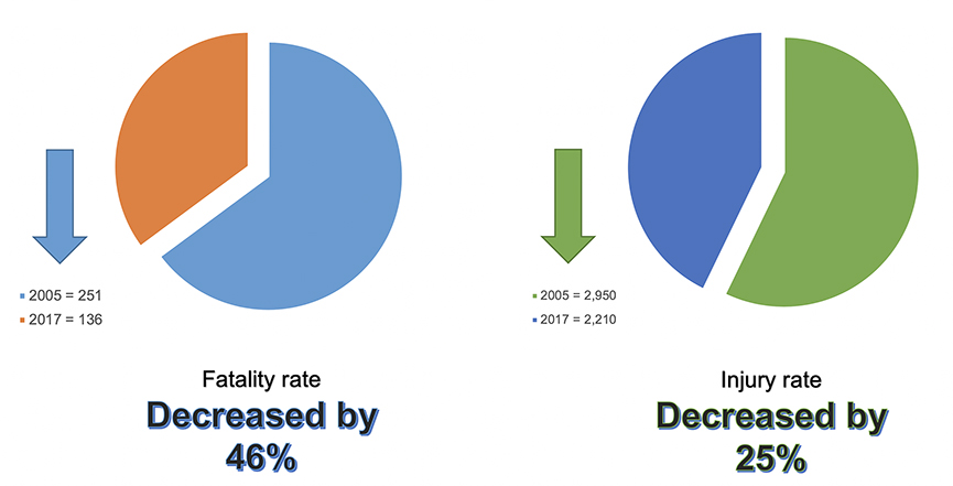
A comparison of the code advancements made between 2005 to 2017 and the related electrical fatalities and injuries over the same time period (as documents in the ESFI report referenced earlier) suggest the new code implementations could be contributing to safer systems. The total fatality rate from 2005 to present has decreased by 46% and the total injury rate has decreased by 25% (see Figure 2). While there are some ups and downs throughout the years, the number of deaths and injuries are overall trending downward. Newer regulations along with more widely adopted safety programs and education are greatly impacting electrical safety in the workplace. In the grand scheme of saving lives, any perceived cost and burdens of these code requirements are entirely worth it.
Some of the code changes that are likely contributing to the reduced fatalities and injuries include: heightened requirements for circuit protection, arc reduction enhancements, additional warning signs and labeling requirements, accessibility and safe working clearances and end–use safety devices.
Electrical distribution and circuit protection
When designing a safe electrical distribution system, the engineer has a great deal to consider. The system must be designed with the proper circuit protection strategies. The components must be physically located within the building to provide a safe working environment. The system must include the safe end–use devices to protect the occupant. Furthermore, the engineer must coordinate with other experts such as mechanical, plumbing, fire protection and structural engineers as well as architects, contractors and owners to ensure safe integration of all systems.
When designed properly, electrical circuit protection components of a distribution system will protect against electric shock, thermal effects, overcurrent, fault currents and overvoltage. Applying code–required and best practice circuit protection strategies provides personnel protection and aids to minimize disruption, ultimately ensuring a safe operating system. Some of the circuit protection strategies that have been greatly affected by code changes over the years include selective coordination, arc flash reduction and proper system grounding. Proper application of these strategies increases the overall safety of the system.
Selective coordination for emergency systems was first introduced in the NEC in 2005 Article 700 specifically for life safety systems. The NEC defines selective coordination as “localization of an overcurrent condition to restrict outages to the circuit or equipment affected, accomplished by the selection and installation of overcurrent protective devices and their ratings or settings for the full range of available overcurrents, from overload to the maximum available fault current and for the full range of overcurrent protective device opening times associated with those overcurrents” (NEC Article 100).
Simply put, selective coordination is intended to isolate a fault as close as possible to the condition while not affecting unnecessary upstream equipment. When designing for selective coordination, overcurrent protection devices are selected to operate in a sequential order such that downstream feeder devices have time to clear before the fault condition pushes the upstream OCPD into its trip operating zone.
Methods to achieve selective coordination include design parameters to intentionally delay upstream breakers from reacting too quickly by either using electronic breakers or simply oversizing devices. However, one unintended result of these strategies is that they tend to increase dangerous arc flash hazards present at the equipment due to extended clearing times.
To counter the potential negative impacts of this aspect of selective coordination, the NFPA code council added a requirement in the 2014 edition of the NEC to protect personnel with “arc energy reduction means” (Article 240.87). This requires any OCPD 1,200 amperes or higher to include an approved means to reduce clearing time, thus reducing the arc energy present.
The code gives various options to accomplish this, including automated systems such as zone selective interlocking and differential relaying, but a manual means also is acceptable. These provisions reduce the arc flash hazard to workers by eliminating intentional trip delays, either automatically or with manual intervention when a worker is present. When the settings are overridden, the device responds faster, reducing the energy of the arc flash, thereby keeping the personnel safer to perform tasks within the arc flash boundary.
As the design engineer works through the system design, he or she must use experience and judgment to optimize the inherent trade-off for reliability and safety and finding the right balance between potentially competing safety interests. If the system design is based solely on safety by minimizing arc flash, it will be difficult coordinating devices and potentially be plagued with nuisance tripping or costly, unplanned downtime. Likewise, a design singularly focused on uptime places people, plant and equipment at risk of higher arc energies.
In addition to selective coordination and arc flash hazard reduction, proper system grounding is a major player in safe system design for personnel and equipment protection. Grounding is the intentional connection of a current-carrying conductor to ground. The main reasons for grounding, according to the NEC, is to establish an effective ground-fault current path for faults to open OCPDs, limit the voltages caused by lightning or by accidental contact of the supply conductors and to stabilize the voltage under normal operating conditions.
Properly grounded equipment provides a ground reference for exposed noncurrent-carrying parts of the electrical system and provides a low-impedance path for ground-fault current to get back to the source. Grounding enhances safety as it reduces the likelihood that conductive parts of the system will be energized when a user touches them.
Grounding is commonly a misunderstood topic and the NEC devotes Article 250 to grounding requirements. The engineer must ensure that the system is not only designed to meet the requirements of the NEC, but also observed during construction to make sure the grounding systems are properly installed.
Equipment room design
In addition to providing safe components within a distribution system, the room that houses the equipment must also provide for a safe operating and working environment. NEC Article 110 is dedicated to requirements for electrical installations and covers “requirements for the examination, approval, installation and use, access to and spaces about electrical conductors and equipment…”
The requirements are largely focused on the installation of the equipment and wiring. Being familiar with the requirements is valuable to the design engineer when reviewing on-site installations by the installing contractor. The requirements in Article 110 directly impact the design of equipment rooms themselves.
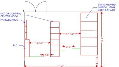
Specifically, Article 110.26 focuses on “spaces about electrical equipment.” The requirements contained in this section are applied by the design engineer to layout equipment rooms. Communication and coordination with the architect is a must to ensure the equipment is housed in a properly designed space. Necessary height, width and depth of working spaces as well as entrances to and egress from working spaces are outlined.
Little has changed in this section of the code over the years apart from egress requirements. The 2002 NEC first introduced the requirement for panic hardware and the doors opening in the direction of egress for equipment rooms with large equipment (see Figure 1). Then in 2014, the NEC updated this same egress requirement to encompass even more equipment rooms.
The requirements contained in Article 110.26 also cover dedicated equipment space. Certain spaces above and in front of electrical equipment are required to be dedicated to the electrical installation and foreign installations, including but not limited to piping and ductwork, are not permitted in this space. Close coordination between the electrical engineer and other designers is essential to meeting this section of the code.
For instance, the teams should work together to ensure the mechanical engineer is not designing ductwork running over equipment or that the architect is not locating a toilet room directly above an equipment room, which would require sanitary waste piping to run through the dedicated electrical zone.
One last item worth mentioning when it comes to equipment rooms is that of the labeling requirements found within Article 110.16. This article states that equipment “shall be field or factory marked to warn qualified persons of potential electrical arc flash hazards.” These labels are incredibly important for educating personnel of the potential dangers so they can adequately protect themselves while working on the equipment. Because many of the labels must be field applied, it is important to verify the requirements of the codes are being adhered to throughout construction and at the end of a project.
Utilization devices
Once the distribution systems are designed to operate reliably and safely and the equipment rooms are properly planned, the engineer must not neglect the safety of the end user. As noted in Figure 1, virtually every code edition over the past two decades has enhanced the requirements for personnel protection at the end–use safety devices. Three types of devices are repeatedly updated with new requirements in virtually every code cycle. These include ground fault circuit interrupter, arc fault circuit interrupter and tamper–resistant devices.
A GFCI receptacle has internal protection designed to de-energize the circuit within an established period of time when a ground fault is sensed. The main requirements for GFCI reside in NEC Article 210.8. GFCI protection is required for commercial facilities in bathrooms, kitchens, rooftops, outdoors, within 6 feet of a sink, wet locations, locker rooms, garages and service bays. Other articles of the NEC also list GFCI requirements for specialty locations, such as vending machines, drinking fountains, dwelling units and mobile homes — and the list continues to grow.
AFCI protection is similar in that it is “intended to provide protection from the effects of arc faults by recognizing characteristics unique to arcing and by functioning to de-energize the circuit when an arc fault is detected” (NEC Article 100). AFCIs typically are applied either at the receptacle or circuit breaker level and are designed to prevent electrical fires that are caused by potentially dangerous arc-faults in an electrical circuit. Requirements for AFCI devices can be found in NEC Article 210.12. They are required in dwelling units and dormitory units, but not in a lot of commercial construction.
Lastly, tamper–resistant devices are required for safety in areas where the user may misuse a receptacle, such as a curious child or mentally disturbed individual. A tamper-resistant device contains a shutter mechanism inside of the receptacle that blocks access to the live contacts unless an appropriate plug is inserted. Requirements for tamper-resistant receptacles are found in NEC Article 406.12 and include dwelling units, guest rooms and suites, pediatric locations, child care facilities, preschools, elementary education facilities, waiting areas and corridors in select facility types and dormitories.
Electrical safety does not end with design
The electrical designer plays a very important role in the safe operating aspects of an electrical distribution system ranging from the point at which the service enters the building to the end use devices. However, electrical safety does not end with design.
Maintaining a safe working environment requires protocols for safe day–to–day operations and safe handling and maintenance of equipment. Every building is different and there is not a step-by-step process to follow when designing electrical distribution systems. By dissecting the applicable codes and understanding their purpose and intent, particularly the safety goals behind them, the engineer will be able to design a truly safe and reliable electrical distribution system built to last.