The University of Texas Frontera supercomputer requires massive amounts of electricity and posed a challenge to engineer the power supply in a limited space.
Learning Objectives
- Learn how design analysis is as good as documenting existing conditions.
- Know leveraging of existing distribution infrastructure to reduce investment needs.
- Understand fast–track projects are a collaborative effort that involves the client, engineers, vendors and contractors.
A growing trend in data centers is the high demand for high-performance computing. HPC is the ability to process data and perform complex calculations at high speeds. HPC solutions are known as supercomputers.
The University of Texas at Austin’s Frontera Supercomputer at the Texas Advanced Computing Center is the fastest university computer in the world and fifth-fastest in the world. Frontera Supercomputer is the November 2019 addition to the top 500 list.
A supercomputer comprises thousands of compute nodes that work simultaneously in parallel to complete multiple complex operations. HPC solutions are used for wide range of industries and academic research. Technologies such as “internet of things,” artificial intelligence, machine learning and 3D imaging are using HPC platforms to search for a cure for cancer, create new materials and develop autonomous vehicles.
Supercomputers require high-density power per rack over 25 kilowatts compared to a data center rack of 15 kW (Frontera is 64 kW). The high-density demand for excessive heat removal exceeds the limits of traditional forced air-cooling. Direct liquid cooling at the compute nodes level provides effective and efficient solution for supercomputer cooling.
Engineers and designers should expect two trends for supercomputer projects: On-site generation and direct liquid cooling. At peak operation, supercomputers can consume up to 20 megawatts of electricity. This type of large load demand can be problematic for the utility grid operation during peak periods. The rapid growth of demand for supercomputers will require incorporating on-site generation in the design to mitigate the shortage of utility grid supply during peaks.
Carbon footprint was also an issue to address. In addition to being supplied by the central power plant, the research center also purchases about 30% of its power from wind credits from wind power in West Texas and draws on solar power from panels in its parking lot. Power sources feed 480 volts to the transformers, which step down electricity to a still-powerful 415 volts to the supercomputer.
Computational power
The University of Texas at Austin’s Frontera supercomputer at the Texas Advanced Computing Center is the fastest university computer in the world and fifth-fastest in the world overall. Frontera achieved 23.5 PetaFLOPS, a measure of the system’s floating-point computing power, with a theoretical peak performance of 38.7 PetaFLOPS. A PetaFLOPS is one 1,000 trillion operations per second. A human would have to complete one calculation every second for 1 billion years to match Frontera’s output in one second.
Frontera was dedicated by the National Science Foundation in September 2019 for multiple academic research projects that covers global warming, cancer, bio informatics and many other research fields. The Texas Advanced Computing Center was awarded $60 million grant funded by NSF to develop the Frontera supercomputer. This included providing infrastructure for power and cooling of the supercomputer equipment in an existing data center.
Selecting a power supply
At peak operation, Frontera consumes 6.5 MW of continuous power to run 91 new rack servers that comprise the system. Power is supplied from the UT Austin J.J. Pickle Central Utility Plant via a power distribution system.
New high-efficiency transformers minimize load loss and heat loss to reduce overall energy loss for the computers. Engineers presented two different power solution options. The first was a build-from-scratch design that would involve new electrical duct banks for four new 2,000-ampere feeders from the central plant, use two existing 2,000-amp feeders within the data center and placing six new outdoor dry-type 1,350-kVA transformers and power distribution equipment outside the building.
Disadvantages of this approach included an extended shutdown and interruption of data center operation, a complex scope of work that would involve multiple engineering discipline coordination and design, disruption of the research campus operation and over budget construction cost.
The second option would use available space within the data center for placing six new dry-type indoor 830-kVA and two dry-type indoor 750-kVA transformers, coupled with the existing three 2,000-amp feeders and new 2,000-amp feeder. The plan would modify chilled water piping, plug-in busways and associated electrical components and high-efficiency transformers to the existing setup that connected to the central plant located 200 feet away.
The advantages of this approach were minimum shutdown and interruption of data center operation, limited scope of work and reduced construction cost. Texas Advanced Computing Center chose the second option, which saved 49% of the construction cost for new electrical and structural infrastructure.
Collaboration the key to success
This fast-tracked and complex project was a highly collaborative effort between the client, engineer, contractor and vendors. Close communication among the various entities was a necessity while working in the small space under the tight time frame. Engineering challenges included:
- Active data center: A demolition plan detailed how to remove structures and connect server racks to mechanical chilled water pipes and reuse some of those for the new supercomputer racks, as well as to isolate, relocate and protect key equipment and assets, all while the data center remained fully operational.
- Tight squeeze: Flooring under the transformers was strengthened with steel stands to hold the larger heavier racks, but only 3 inches of clearance between the large chilled water pipes and the floor struts made for a tight design and little leeway. Similar close clearances on upper server racks leaving little room for power and network cable trays. Building information modeling helped develop section views for each area to coordinate construction and use the limited space, while 3D modeling aided in designing for the ¼-inch clearance.
- Schedule: To meet federal grant stipulations requiring the supercomputer pass high-performance benchmark testing on a strict schedule, the construction schedule was held to less than six months, with mechanical, electrical and plumbing construction limited to just four months.
- Budget: Most of the $60 million budget was earmarked for computer equipment, leaving $6 million to upgrade electrical and mechanical elements.
- Benchmark dates and lead time: The long lead time on large items such as transformers and direct cooling equipment required a commitment to specific design components before the actual design was finalized. It was essential that any subsequent changes work with previously ordered equipment.
- Standards: The compatibilities of equipment built to international standards had to be confirmed to meet U.S. standards. During installation, the pin and sleeve connectors for the server racks were different from those provided with the busway plug-in disconnects. Pin and sleeve connectors followed two different International Electrotechnical Commission 60309 standards, which has two series for amperage ratings and connector layouts. One is for North America and the other addresses international applications. The configurations did not match.
- Remodel: Remodeling is infinitely more complicated than new construction. The existing chilled water system made it difficult to optimize the layout of the new cooling system and placement of the transformers. The existing electrical and mechanical distribution systems had to be modified and upgraded in the computing center room for an ultradense cluster.
Innovative design and construction techniques methods were used to complete the fast-track project. The existing electrical and cooling systems were modified and upgraded. Existing equipment was removed, new equipment was installed and hundreds of miles of cabling were artfully hidden from view in the ceiling and flooring.
The team provided new feeders from the electrical distribution system by using the existing infrastructure and identifying other feeders from adjacent space. This solution eliminated the extended interruption of other supercomputer operations co-located in the same data center space. Also, the existing chilled water loop was modified to provide new direct liquid cooled system and ran associated piping in the available limited space by developing a 3D model.
3D modeling helped avoid design conflicts
Building a detailed 3D model based on record documents, gathering information in the field and adding new equipment and associated electrical and mechanical infrastructure helps develop sectional views to eliminate any possible conflicts that may occur during construction.
A demolition plan detailed how to remove structures and connect server racks to mechanical chilled water pipes and reuse some of those for the new supercomputer racks, as well as isolate, relocate and be sensitive to key equipment and assets in an operational facility.
Flooring under the transformers was strengthened with steel stands to hold the larger heavier racks, but only 3 inches of clearance between the large chilled water pipes and the floor struts made for a tight design and little leeway. Similar close clearances on upper server racks leaving little room for power and network cable trays. BIM models helped develop section views for each area to coordinate construction and use the limited space, while 3D modeling aided in designing for the ¼-inch clearance.
How to design a data center
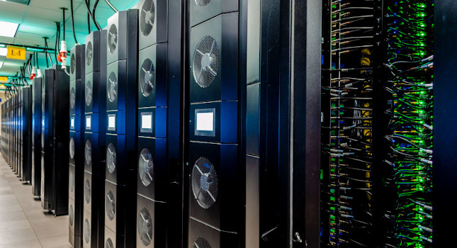
Aesthetics usually have no role in a data center. The 2,400-square-foot area housing the Frontera is dominated by row upon row of black monolith 10-foot-tall servers, prompting the nickname “Caves of Steel.” But consideration was given to visual appearance when it also played a role in function and budget.
The unusually tall server racks left little overhead room for power and network cable trays. It was proposed to leave the ceiling space open to free up space, which the Texas Advanced Computing Center initially agreed to. However, it would also allow the possibility of dust and other pollutants to enter.
Instead, a 3D model was created representing 197 drops above the server racks to confirm that no conflicts existed between the steel structure supporting the roof and the busways. Then the busways and drops were installed in the ceiling space within the structure.
Cutout sleeves were installed in the ceiling tile for the drops to create a clean and crisp appearance that otherwise would have been a spider’s web of wiring above the entire data center. Likewise, additional floor tiles to match the existing custom-built tiles were no longer available. A floor template was created for each rack so that the holes already cut into the existing tiles could be matched with required new cutouts for the chilled water loop. This eliminated the need to purchase new tiles that wouldn’t match the existing pattern.
Electrical, cooling system modeling critical
Modeling of the electrical system is a critical component for designing electrical power systems for a supercomputer. It is extremely challenging to perform a transient analysis for high-density load that varies by 4 MW of power in less than a quarter cycle in some instances. This results in voltage drop and wave form distortion beyond some auxiliary equipment tolerances that can lead to interruption of service and premature failure. Selecting auxiliary equipment that can ride through such extreme conditions is crucial to providing a viable design solution.
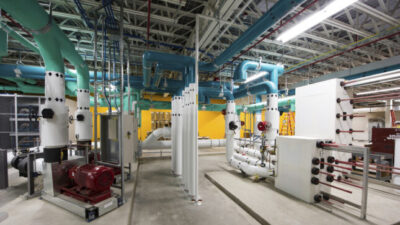
The supercomputer has more processors packed into a smaller footprint than ever at the computing center. This high-density demand for excessive heat removal exceeds the limits of traditional forced-air cooling. For such a dense system, innovative cooling technologies at the computer node level were required. These include liquid cooled copper plates that sit on each chip, circulating fluid that whisks the heat away, requiring nearly 2,500 liters of coolant as well as fans on each rack, something never used at Texas Advanced Computing Center.
In terms of the cooling system model, the direct liquid cooled system comprised a primary loop and a secondary loop. The primary cooling loop is the traditional chilled water system, which runs through cooling distribution units (CDU) in each of the 91 racks.
Each CDU has a heat exchanger and redundant circulating pumps. Both the primary and the secondary cooling loops run through the heat exchangers of the cooling distribution units. Mechanical modifications were made to the chilled water system to feed the cooling distribution units (CDU) for more effective heat removal. The secondary loop circulating pumps run the special coolant to the rack cooling door and manifolds for direct loop cooling of each compute node. There are 88 server nodes per rack, 8,008 in total.
Meeting power project goals
The design and construction were completed spring 2019 and precedes a much larger computer installation at the center.
Whether the facility is new or existing, engineers are always faced with challenges to design mechanical and electrical infrastructure to meet the requirements for data centers loads. In both cases, engineers must work closely with client, contractors and vendors to provide design solutions without compromising the intent of the design and equipment performance.
Also, confirming compatibilities of equipment build to international standards with U.S. standards. In existing data centers, the biggest challenges are to isolate, relocate and be sensitive to key equipment and assets while the data center is still powered up.
Tarek G. Tousson is principal electrical engineer/project manager at Stanley Consultants. His expertise is in motors, generators and uninterruptible power supply systems and he has more than 25 years of experience designing electrical power distribution systems for mission critical facilities and other types of buildings.