Choosing the right pipe system and design is essential to ensure excellence in mechanical, plumbing, fire protection and beyond

Learning objectives
- Summarize commonly used piping materials.
- Know the pipe sizing recommendations for mechanical hydronic applications.
- Learn about pipe supports and thermal expansion considerations.
It’s easy to forget about pipe systems. Once installed, they are rarely seen or thought about. But that belies their importance, especially when it comes to choosing the right pipe system and design to ensure excellence in mechanical, plumbing, fire protection and beyond.
Simply defined, pipes are pathways through which fluids are contained and flow in a system. The fluids may be water, glycol solution, fuel oil and refrigerant liquid. A network of pipes, fittings, joints, valves and supports is defined as a pipe system.
There can be multiple pipe systems on a typical project and they can be segregated by disciplines such as civil (domestic water, stormwater, sanitary, industrial water, wastewater, etc.); mechanical or heating, ventilation and air conditioning (chilled water, condenser water, hot water, steam, condensate, natural gas, fuel oil etc.); plumbing (domestic cold water, hot water, waste, vent, etc.); and fire protection (sprinkler water, compressed air, etc.).
Pipe system design is dependent on the requirements and design criteria that are specific of each discipline. The design of pipe systems is also governed by codes such as those published by ICC and standards and guidelines published by trade associations such as ASME, ASTM, NFPA, MSS, AWWA and ASHRAE.
An optimum pipe system design is critical to the operation and longevity of the overall infrastructure and requires a multipronged approach. With appropriate maintenance, piping is typically expected to last the age of the building, while other equipment is replaced at the end of its service life. As pipe systems span multiple disciplines with varying requirements, developing an all-encompassing design guideline would be a monumental task.
There are numerous factors that need to be considered when selecting a pipe system, such as:
- Type of fluid.
- Fluid pressure.
- Fluid temperature.
- Fluid flow rate.
- Code and authority having jurisdiction requirements.
- Service life.
- Project cost.
- Project schedule.
- Local labor expertise.
Piping materials
Pipes can be broadly classified as metallic type and nonmetallic type. Commonly used metallic pipes are carbon steel, copper and ductile iron. Metallic pipes and fittings have been used for ages and continue to be used extensively.
Steel pipes manufactured in accordance with ASTM A53 standard specification are typically used in the mechanical industry. ASTM A53 covers nominal pipe size from 1/8 inch through 26 inches. Based on the manufacturing process and size, steel pipe can be classified as Type S (seamless), Type F (furnace butt weld) or Type E (electric resistance weld). Type F is available in Grade A while Type E and Type S are available in Grade A and B. The two grades have slightly different chemical composition of steel such as maximum percentage of carbon. Grade B is widely used due to its higher tensile strength.
The wall thickness of steel pipe is identified by schedule or weight class. Depending on size, steel pipe is typically available from schedule 5 through schedule 160 and wall thickness increases with schedule number. For example, 8-inch steel pipe has an outside diameter of 8.625 inches. However, the wall thickness varies from 0.109 inch (schedule 5) to 0.906 inch (schedule 160).
The working pressure of steel pipe increases with its schedule. ASME B31 identifies the criteria for calculating the working pressure of steel pipe systems. Calculations should include allowance for mill tolerance on wall thickness, corrosion allowance and cutting allowance if using threaded or cut-grooved joints. The ASHRAE Fundamentals Handbook is an excellent reference and it provides working pressure of commonly used steel pipe schedules from nominal pipe size 1/4 inch to 20 inches.
For the mechanical industry, commonly used steel piping is schedule 40 and schedule 80 for sizes 10 inches and below. Schedule 40, STD (standard weight) and schedule 80 are commonly used for pipe sizes 12 inches and above.
Steel pipes are typically joined by using welded, flanged, threaded or grooved-end fittings. A hybrid solution is common, such as using threaded fittings for pipes 2 inches and below and flanged fittings for sizes 2.5 inches and above.
Copper tubes manufactured in accordance with ASTM B88 standard specification for water service; ASTM B306 for drain, waste and vent service; and ASTM B280 for air conditioning and refrigeration service are typically used in the mechanical industry. A minimum of 99.9% pure copper is used for their production. Copper tubes are classified as Types K, L, M and DWV depending on the wall thickness per ASTM standard B88 and B306. Wall thickness and working pressure reduces from Type K through DWV. For example, a 2–inch copper tube has an outside diameter of 2.125 inches. However, the wall thickness is 0.083 inch (Type K), 0.070 inch (Type L), 0.058 inch (Type M) and 0.042 inch (Type DWV).
Similar to steel piping, ASME B31 identifies the criteria for calculating the working pressure of copper tube systems. Copper tubes are available as hard-drawn (rigid) or annealed (bendable). Hard-drawn tubing has a higher working pressure compared to annealed tubing. Copper tubes are typically joined by using brazed, soldered, grooved-end or press-connect fittings. When brazing is used for joining hard-drawn copper tubing, the high temperatures associated with the joining process anneals copper at the joint and therefore the pressure ratings of annealed tubing are used.
Ductile iron pipe is used sparingly in the mechanical industry, though it is extensively used in plumbing and civil applications. AWWA C150 deals with DI pipe.
Common nonmetallic pipe systems used in the mechanical industry are polyvinyl chloride, chlorinated polyvinyl chloride, cross-link polyethylene (PEX), high-density polyethylene, polypropylene, acrylonitrile butadiene styrene and others. Nonmetallic systems continue to gain popularity in the mechanical industry and proprietary plastic blends continue to be developed.
Nonmetallic pipes offer several advantages such as low cost, light weight, inherent corrosion protection, immunity from galvanic effects, chemical inertness, low thermal conductivity, low friction losses and ease of installation.
However, the application needs to consider the disadvantages, such as low baseline strength and severe degradation at elevated temperatures, high coefficient of expansion and limited ultraviolet resistance if installed outdoors. Nonmetallic pipes are typically joined by solvent, threaded and flanged connections.
Identifying the right pipe
The various pipe materials have inherent advantages and disadvantages. During design, it is critical that the attributes of pipe systems be reviewed in detail to ensure that the system that best satisfies the project requirements is selected.
Sizing
- For hydronic applications, velocity and pressure drop (due to friction losses) are the two primary factors that are considered for sizing pipes. The intent is to select the smallest possible pipe size while ensuring that velocity and pressure drop are within limits.
- The general recommendation is to limit fluid velocity to 10 feet per second for metallic pipes and 5 feet per second for nonmetallic pipes to minimize the impact of noise, erosion, cavitation and water hammer, depending on the application. Water hammer and pressure surges need to be specifically reviewed for nonmetallic pipes — hence the general recommendation to limit velocity to 5 feet per second. A minimum velocity of 2 feet per second is recommended for closed–loop systems to ensure that entrained air can flow to the air–separation device and be vented from the system.
- Another general recommendation is to limit pressure drop to 4 feet water column per 100 feet of pipe to ensure that pump head and power requirement are reasonable. Charts are available to help size pipes of various materials and they are typically used for most calculations. For complex applications requiring detailed analysis, pressure drop through piping can be calculated by using the fundamentals of hydraulics and equations such as Darcy-Weisbach and Hazen-Williams. The impact of fittings and pipe accessories such as valves can be accounted as equivalent pipe length or pressure drop equations that use loss coefficients. In addition, standards such as ASHRAE Standard 90.1: Energy Standard for Buildings Except Low-Rise Residential Buildings also dictate pipe sizing. See Table 1 for chilled water and condenser water pipe sizing requirements per ASHRAE 90.1-2016.
Pipe supports
- Pipe supports must be designed to support the static and dynamic loads anticipated during operation. Static loads include weight of pipe system (pipe, valves, fittings, insulation, etc.), weight of fluid and weight of supporting elements. Dynamic loads include wind loads (for piping installed outdoors), seismic loads and forces generated by thermal expansion and contraction.
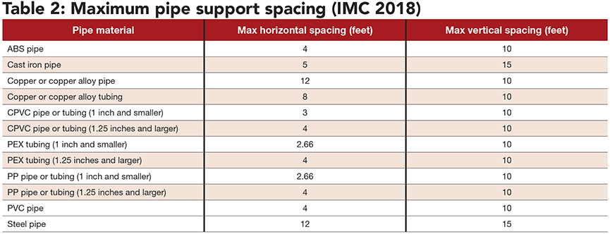
- The impact of these loads and means of support should be coordinated with the building structure. Standards such as ASME B31.9 and MSS SP-58 provide pertinent information related to design and installation of pipe supports. In addition, building codes such as the International Mechanical Code also have requirements associated with supporting pipes. Table 2 indicates the maximum support spacing of common pipe materials as mandated in IMC 2018. Note that nonmetallic pipes require frequent supports compared to metallic pipes.
Pipe expansion
- Pipe length alters with changes in its temperature. For an unrestrained pipe, the magnitude of change depends on the pipe material (coefficient of thermal expansion), original pipe length and magnitude of temperature change. Table 3 indicates the coefficient of thermal expansion of common pipe materials. As is evident, nonmetallic pipes typically have significantly higher coefficients of thermal expansion compared to metallic pipes.
- Significant movement is possible for piping systems operating at high temperatures or in long runs of piping. Failure to account for thermal expansion and associated stresses can lead to failure of pipe supports, equipment connections and pipe joints. It is imperative that the pipe system be adequately flexible to accommodate pipe movement throughout its operating temperature range while keeping the internal stresses and anchoring forces within reasonable limits. Expansion compensation can be incorporated by using L-bends, Z-bends or U-bends at strategic locations along the pipe to increase flexibility or by using fittings such as bellows expansion joints and braided hose assemblies. Pipe stress analysis software can be used for complex applications.
Pipes are essential to civilized life. The idea that choosing the right system and design ensures all of us will be better off is a lead-pipe cinch.


