Hydronic heating systems remain an energy-efficient and effective means to distribute low-grade waste heat throughout a high-performance building.
Learning Objectives
- Recognize how low-grade waste-heat recovery may be applied to building hydronic systems to maximize their effectiveness in building heating.
- Explore the differences between parallel and series hydronic heating systems, and how these approaches may be combined to optimize system performance.
- Understand how pump selections may be optimized with considerations for redundancy.
The Department of Energy’s (DOE) National Renewable Energy Laboratory (NREL) Energy Systems Integration Facility (ESIF) was built to study the integration of renewable energy sources into the national electric grid. The 182,500-sq-ft facility houses high-bay laboratory research spaces with an interconnected electrical grid, a high-performance computing data center (HPCDC), and administrative spaces inclusive of offices, conferencing, and visualization laboratories. True to their mission, NREL stipulated that the facility will be highly energy-efficient, with energy efficiency requirements as follows:
- A minimum building energy performance 30% better than ASHRAE 90.1-2007 with a LEED NC 2.2 Gold rating (achieved 34% better than ASHRAE and a LEED NC 2.2 Platinum rating).
- Power-usage effectiveness (PUE) is a metric to measure data center efficiency and is a ratio of (server energy + server building energy) / server energy. The HPCDC will operate with a PUE of 1.06 or less [performs at a PUE of 1.04].
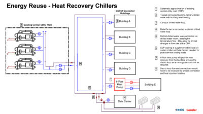
- Energy-reuse effectiveness (ERE) is a metric developed by NREL and The Green Grid to describe data center waste-heat reuse, a ratio of (server energy – recovered server energy) / server energy). The data center will operate with an ERE of 0.9 or less. The facility was able to achieve this by using data center waste heat to provide beneficial heating to the building.
- Office energy-use intensity (EUI) of 25 kBtu/sq ft per year or less [achieved EUI of 23].
- Ability for regularly occupied spaces to have general lighting off from 10 a.m. to 2 p.m. Extensive daylight modeling demonstrated compliance and was confirmed by NREL after occupancy.
NREL ESIF is located on NREL’s campus in the high desert of Golden, Colo. Located just outside of Denver, Golden is predominantly a heating environment with generally dry conditions. NREL realized early on that a highly efficient data center that easily rejects heat is still wasteful regardless of its performance. As the data center is always rejecting heat, their program paired this function with other programs in the same facility that require heating. Why not recover the waste heat and use it to improve the energy efficiency of other spaces?
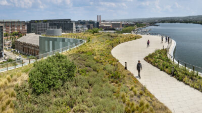
Figure 1: The NREL ESIF in Golden, Colo., combines a laboratory, office, and data center for a mutual energy benefit. Waste heat from the data center is recovered to provide heating to the office and laboratory. Courtesy: Dennis Schroeder, NREL[/caption]
Maximizing the water-heating system
Pump energy varies based on the system flow rate, the pressure drops, and the pump’s efficiency. The system flow rate is determined based on the peak demand of the connected system components. Traditional heating-water systems serve system components in parallel to lower the pressure drop and reduce pump energy. An underlying assumption in this approach is that the terminal devices and building air handling units (AHUs) can use the same quality (or temperature) of water. AHUs, however, only temper the supply air to 55°F and can accomplish the task with a lower quality of water. Terminal units are closest to the spaces needing conditioning, and require the highest quality of heat.
An alternative approach is to serve terminal devices and AHUs in series. The challenge with a series approach is ensuring that the heating water is available to AHUs even with a low demand on other terminal devices. This approach requires increased pressure, forcing system pumps to potentially work harder than they need to. The resulting larger temperature differential, however, enables low-grade waste-heat recovery to remain effective.
The Darcy-Weisbach Equation defines pressure drop as (f x L/D) x (/g x V2/2), or the loss coefficient x the velocity pressure. Taken another way, the pressure drop varies directly with the losses due to the pipe configuration and devices, but with the square of the velocity (or flow rate for a given pipe size). The use of 45-degree taps in lieu of 90-degree tees will lower pressure drop, as will minimizing the length of the piping network. Increasing the pipe size (or lowering the pipe velocity) by one-third lowers the pressure loss for a fixed system geometry by more than 50%.
Using glycol solutions is effective for freeze-and-burst protection of piping systems. Their addition, however, increases pipe friction losses while lowering the heat-transfer effectiveness of coils and heat exchangers. This translates into a higher system flow rate for a comparable amount of heating. System performance must be balanced with protections for freezing, and the combination of glycol and low-grade waste heat makes an already difficult problem harder to achieve.
An alternative approach to using a glycol solution for freeze protection is to provide full waterflow through coils in freezing conditions via a pumped coil. The combination of a small pump and three-way-control mixing valve ensures continuous circulation through every circuit of the coil to reduce the potential of freezing. Heat is then added as needed to maintain the discharge-air temperature setpoint. Configured correctly, this pump only needs to operate at or near freezing conditions and can be switched off at other times. In the event of a coil pump failure, the elevated heating water temperature is delivered directly to the AHU. This is the approach that is used for the NREL ESIF water-heating system.
To be effective, the NREL ESIF project needed to use all these principals to lower energy use and maximize its effectiveness.
Courtesy: Dennis Schroeder, NREL
HVAC system configuration
The water-heating system is configured as a variable primary system with two heat sources and two interconnected heating loops—low-temperature and high-temperature. The low-temperature loop operates year-round at 95°F and is dedicated to the office and conference spaces. The high-temperature loop operates at 95°F with outdoor temperatures above 55°F but can be reset to as high as 130°F during peak winter conditions (reset based on outdoor temperature). The transition point was set at 55°F as it represented a typical supply-air temperature during the summer months. The high-temperature loop is dedicated to the laboratory spaces, laboratory make-up AHUs, entry vestibules, snow melt, etc. These separate loops come back together in a common return using the same water-heating system pumps.
The primary heating source for the water-heating system comes from the +95°F energy-recovery water system serving the HPCDC. All heating obtained from this system is “free,” as it is harvested energy from the data center. Only transport energy is required to get this heat from the data center to the building. A plate-and-frame heat exchanger with a 2°F-approach temperature isolates the data center energy-recovery system from the building water-heating system. Both heating-water loops pass their return through this common primary heat exchanger. Any waste heat that is not recovered is effectively rejected through the data center cooling system.
Once the outdoor temperatures fall below 55°F, the high-temperature loop requires supplemental heating to meet the heating load of its respective spaces. This supplemental heat comes in the form of campus heating water, which operates as high as 160°F based on outdoor temperatures. A plate-and-frame heat exchanger isolates the campus water-heating system from the building water-heating system. While normally dedicated to the high-temperature loop, this supplemental heat exchanger is sized to provide all the heating to the building if the data center shuts down or is operating at a reduced capacity.
With outdoor temperatures above 55°F, the +95°F energy-recovery water is enough to provide heating to the entire water-heating system serving offices and laboratories, and the supplemental heat exchanger is bypassed to lower the pump’s energy. A similar bypass valve is provided around the primary heat exchanger to allow it to be taken down for service and maintenance. When this occurs, a modulating control valve on the low-temperature loop downstream of the supplemental campus heat exchanger restricts flow, allowing the high-temperature loop to blend to maintain the 95°F design temperature.
Energy modeling of the underfloor office areas in Golden calculated an EUI of 35 kBtu/sq ft/YR, roughly 12 kBtu/sq ft per year of which comes directly from the heating source. To achieve an EUI of 25 or less, the office needed to use the data center waste heat completely. Early concepts for the underfloor-air HVAC system heating included a perimeter fin tube, though this required the 95°F heating water to be reset to above 120°F, exceeding the EUI target due to the injection of campus heating water.
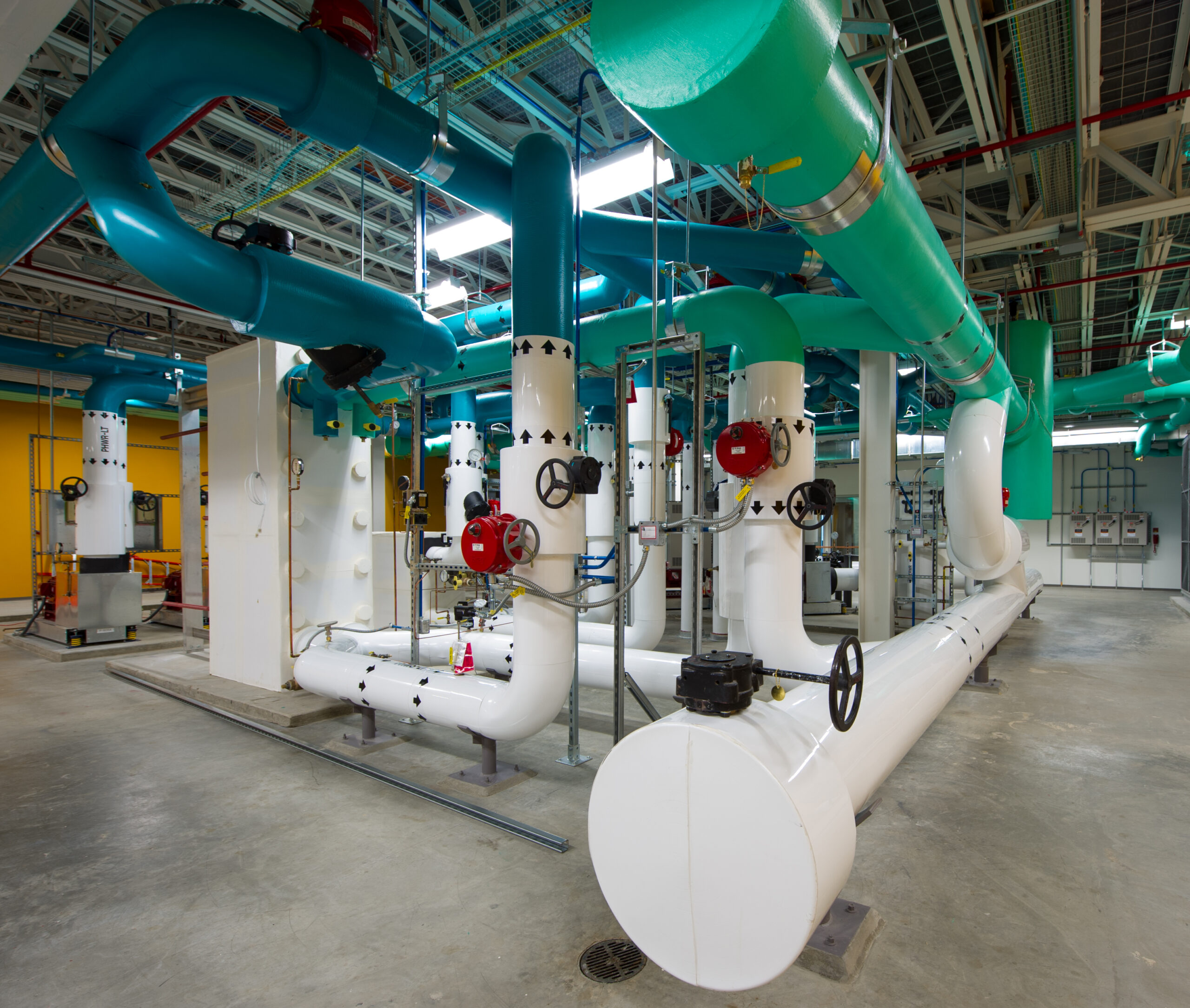
Figure 4: The heating-water system (blue piping) energy-recovery heat exchanger (left) captures data center waste heat (green piping). The campus heating water heat exchanger (right) provides supplemental heat to the building as needed.Courtesy: Dennis Schroeder, NREL
Supplemental perimeter cooling was planned for the office areas in the form of two-pipe active chilled beams. Early studies integrated 95°F heating in the form of a four-pipe active chilled beam with isolated coils, but the approach fell short of the heating and cooling capacities due to the limited coil areas. Only two-pipe active chilled beams (with one coil) met the cooling capacity requirements. Coupled with an excellent envelope, the team found that this approach also met the perimeter heating load with no supplemental campus heating, allowing data center waste heat to provide all the office heating. As a result, zoned two-pipe changeover valves were added to the project based on perimeter exposure.
Primary air for the active chilled beams comes from small, transfer air fans in the return-air plenum. This approach eliminated reheat and decoupled perimeter conditioning from the underfloor air system. The underfloor air system is shut off overnight while space conditioning continues via the low-pressure transfer air fans and active chilled beams. The low-grade heating water is more than enough to provide outside-air heating and preheating of the underfloor plenum (and floor slab) during the winter months.
The approach to the high-temperature loop serving laboratories and building entries was to minimize the return-water temperature. The heating-water supply temperature required 130°F to meet the high-bay laboratory heating loads on a design winter day. Using a traditional 20°F temperature differential results in return-water temperatures of more than the 95°F low-grade heating water supply, ending the potential energy recovery at the time it could be used the most. Designing for a 40°F temperature differential can lower the return-water temperature to just below that of the low-grade supply temperature, providing minimal, if any, energy recovery when it is needed most.
A change was required to maximize the temperature differential on the laboratory portion of the system. Two options were proposed to address this condition. The first was to route a set of dedicated low-grade heating pipes to the 100% outside-air make-up AHUs, focusing the high-temperature loop on the high-bay laboratories with some supplemental capacity for the make-up AHUs. The return water from the high-bay laboratories remained at or above the low-grade supply temperature in this approach, but then it blended with the low-grade return from the make-up AHUs to achieve a 50°-60°F temperature differential overall. The approach met the energy requirements for this project but was ultimately rejected due to the high cost of the additional piping infrastructure.
The second option changed the high-temperature loop configuration from feeding all heating coils in parallel to a mix of parallel and series coils. All the high-bay laboratory heating coils were served first in parallel with a design temperature differential of 20°F. The up to 130°F high-temperature supply generated closer to a 110°F “return” on a design day. This high-temperature “return” from laboratory heating coils was routed past the 100% outside-air make-up AHU heating coils. Pumped coils at the make-up air units then used the high-temperature “return” directly. High-temperature supply was available to provide supplemental heating or feed the coil directly with a coil pump failure. This added a minimal amount of piping but yielded an even large temperature differential—as much as 60°F across the unit.
On a near design day that first winter, this generated a temperature differential of nearly 80°F on the high-temperature loop. When added to the low-grade heating-water return, the combined heating-water return was over 65°F, a nearly 30°F temperature differential on the low-grade temperature loop. And this temperature differential was achieved after the addition of supplemental campus heating.
Figure 5: The heating-water system flow diagram first recovers waste heat from the data center, then uses campus heating water to boost temperatures for the high-temperature loop.Courtesy: SmithGroup
Optimizing pump selections for energy efficiency and performance
Early pump selections for the water-heating system were disappointing. While most pump efficiencies for other systems in the facility were greater than 80%, initial pump selections for the water-heating system were closer to 65%. Moving from an end-suction type to vertical inline did not move the bar any. As these pumps will operate year-round to recover waste heat from the data center, they need to be efficient. The flow is based on the system demand, which left only the pressure drop as the variable that could potentially be changed to optimize the pump selections.
At this point, the focus shifted to minimizing the pressure drop further and fine-tuning the calculations. The process of the heating-water system optimization began as follows:
- Optimize the piping distribution to remove unnecessary fittings. The pipe routing for the design leg was cleaned up, which in this case, was the high-bay laboratories.
- Take a closer look at the calculations themselves and replace placeholders for coil and valve pressure drop with actual values from equipment selections.
- Back off on the safety factor for the pump based on more detailed calculations.
Figure 7: With the failure of a local pumped coil at a laboratory make-up AHU, the primary and standby pump operate together to provide the increased flow and pressure needed to offset the failed pumped coil. Each pump rides its curve back to the failure design point.
Courtesy: SmithGroup[/caption]
Bringing on the lag system pump in this condition allowed both system pumps to ride up on their pump curves while providing the increased flow and pressure required. The increased pressure and flow were enough to meet the design case while simultaneously maximizing the pump efficiency. The operation was validated during test and balance, with the combination of both lead and lag system pumps able to meet the design day heating load with full flow on a single make-up AHU.
The challenge for NREL ESIF was to design and configure a water-heating system to make the best use of the 95°F low-grade waste heat from the data center. Carefully selecting and investigating system components allowed the office and conferencing spaces to operate year-round solely on the low-grade waste-heat source. The high-temperature loop to the laboratories, needed for the winter months, was configured to generate a significant temperature delta compared to traditional systems, allowing for continued waste-heat recovery even with the addition of campus heat.
While early pump selections were not ideal, the team focused on adjusting the parameters, pressure drop in this case, to optimize pump selections. Even when challenged to increase the system pump sizes to address a coil pump failure, the team was able to prove out the lead-lag operation while maintaining a high-efficiency pump, an approach that saves energy year-round. The approach was verified during test and balance, confirming that the smaller, more efficient pump will support the design day condition.
NREL ESIF has provisions to export data center low-grade waste heat to other buildings on campus in the future. Laboratory buildings on campus can use low-grade waste heat directly in summer months, while other office buildings with radiant slabs could use the low-grade waste heat to provide full heating in winter months. Data center waste heat, a resource to the building, can ultimately become a campus resource.
SmithGroup worked together with NREL to implement a process to export waste heat to the campus in summer months through the campus water-heating system. NREL has since expanded on this, using the underground campus heating-water network as a heat sink for the data center from June to September. In September, when heating loads begin to appear, the low-grade waste heat from the data center allows the campus boilers to remain off for an additional month as compared with operations before NREL ESIF.