Pressure-regulating devices are required to maintain safe system working pressures
Water pressure insights:
- Water-based fire protection systems rely on pressure-regulating devices to prevent component failure and ensure proper performance by limiting pressure.
- These devices, such as pressure-reducing valves and pressure-relief valves, are crucial for maintaining safe pressure levels within automatic sprinkler and standpipe systems, as dictated by standards like NFPA 13 and NFPA 14, especially considering the varying flow conditions and system demands.
![]()
Water-based fire protection systems often require pressure-regulating devices to limit pressure on system components. Pressure limitation is necessary to prevent the failure of system components and to assure proper system performance. The 2019 editions of NFPA 13: Standard for the Installation of Sprinkler Systems and NFPA 14: Standard for the Installation of Standpipe and Hose Systems define a pressure-regulating device as:
“A device designed for the purpose of reducing, regulating, controlling or restricting water pressure.”
NFPA 13 and NFPA 14 also specify the pressure limitations within the respective systems.
NFPA 13 requires automatic sprinkler system components to be rated for no less than 175 pounds per square inch (psi) or rated for the maximum system working pressure the components are exposed to, whichever is greater. Most automatic sprinkler system components are rated for a maximum pressure of 175 psi, especially sprinklers.
NFPA 14 requires standpipe systems to be limited to a maximum working pressure of 400 psi and express mains are permitted to have pressures more than 400 psi. However, hose connection (valve) outlet pressures cannot exceed 175 psi.
Successful system pressure regulation requires selection of the appropriate device type for the application, accurate design implementation and proper installation and testing to verify functionality and performance.
Types of pressure-regulating devices
There are three common types of pressure-regulating devices, including pressure-restricting valves, pressure-reducing valves and pressure-relief valves. Each valve type has different uses and means of operation.
Pressure-restricting valves reduce downstream water pressure in flowing conditions only. For instance, if a pressure-restricting hose valve is set to a maximum pressure of 100 psi, the downstream pressure while water is flowing will be limited to 100 psi. However, if water stops flowing, the downstream pressure could increase beyond 100 psi, depending on the system’s static working pressure.

Pressure-reducing valves reduce downstream water pressure when water is flowing and when water is not flowing. For example, a pressure-reducing valve installed at the base of a sprinkler system riser would limit the water pressure on the sprinkler system to the valve’s set pressure during normal (no flow) conditions and while water is flowing due to a sprinkler activation.
There are two common types of pressure-reducing valves, nonpilot operated and pilot-operated. Nonpilot-operated valves are typically limited to lower flow rates and have a significant residual pressure drop between the valve inlet and outlet.
Pilot-operated valves often referred to as pressure control valves, are suitable for a wide range of flow rates, depending on the valve size selected. Pilot-operated valves maintain the set pressure downstream of the valve with minimal residual pressure loss through the valve when the inlet pressure drops below the set pressure.
When selecting a pilot-operated pressure reducing valve that will serve multiple flow scenarios, the valve must be capable of supporting the lowest and greatest flow rates (e.g., flow of one sprinkler to greatest system design flow demand) or a bypass must be provided with a pressure-reducing valve capable of supporting the lower flow rates.
Pressure-relief valves relieve pressure from a system by discharging water from the system. These valves are only permitted in systems as a fail-safe device typically used to relieve unanticipated excess pressure, such as pressure increases due to thermal expansion or a diesel-driven fire pump runaway scenario. A runaway scenario is an instance resulting in unintended high engine speeds causing excess output pressures.
Applications of pressure-regulating devices
The following describes the applications where a pressure-regulating device is required and considerations for compliant implementation.
Automatic sprinkler systems: NFPA 13 requires every wet pipe automatic sprinkler system to have a minimum ½-inch pressure-relief valve set to operate at 175 psi, or 10 psi greater than the maximum system working pressure, whichever is greater. The relief valve must be installed in the system downstream of the system check valve. Alternatively, an auxiliary air reservoir installed to absorb system pressure greater than 175 psi is permitted in lieu of a pressure-relief valve.
Automatic sprinkler systems supplied from a source with a pressure exceeding the listed pressure rating of system components must be provided with a pressure-reducing valve to maintain the system pressure. As mentioned previously, automatic sprinkler system components are typically listed for a working pressure of 175 psi. Therefore, NFPA 13 requires the outlet pressure of the pressure-reducing valve to be set to a maximum pressure of 165 psi.

In addition, when a pressure-reducing valve is installed in an automatic sprinkler system, NFPA 13 requires the following:
-
A pressure gauge must be installed on the inlet and outlet of each pressure-reducing valve. In most cases, the sprinkler system pressure gauge downstream of the pressure-reducing valve satisfies the need for the pressure gauge on the outlet side, but a pressure gauge dedicated to the inlet side must be installed.
-
A minimum ½-inch pressure-relief valve is required downstream of the pressure-reducing valve and must be set to operate at a maximum pressure not exceeding the rated pressure for the system components (e.g., 175 psi). Also, the relief valve must be installed upstream of the system components requiring protection from excess pressure. The discharge of the relief valve should be piped to an acceptable drain. Refer to the pressure-reducing valve manufacturer for recommended relief valve sizing that may exceed the requirements of NFPA 13.
-
An indicating control valve is required on the inlet side of each pressure-reducing valve. If the pressure-reducing valve satisfies the listing requirements for an indicating control valve, an indicating control valve is not required on the inlet side of the pressure-reducing valve.
-
A means for testing the pressure-reducing valve at the system demand flow rate shall be provided downstream of the pressure-reducing valve.
Standpipe systems: Pressure-regulating devices are commonplace in standpipe systems serving high-rise buildings. This is due to the system pressure demands necessary to deliver water to the remote highpoints of a system at the required minimum operating pressure.
Often, the required system working pressure at grade level must exceed 175 psi to provide 100 psi at the highest hose connection. Per the standard, 100 psi is the required discharge pressure at hose connections in Class I standpipe systems. Consequently, the excess pressure must be controlled to safeguard the system components on the lower levels.
Every standpipe application should be evaluated for the best means of controlling the system pressures. There is no one-size-fits-all approach.
Depending on the water supply and system configuration, one or any combination of the following would be applicable to limit pressures at hose valves to less than or equal to 175 psi:
-
Pressure-reducing hose valves on the level(s) subject to pressures exceeding 175 psi.
-
A pressure-reducing valve upstream of no more than two hose valves on the level(s) subject to pressures exceeding 175 psi.
-
A pressure-reducing valve assembly (PRVA), in accordance with NFPA 14 Section 7.2.4 (2019 edition), where serving more than two hose valves.
Pressure-restricting hose valves are limited to applications where the pressure does not exceed 175 psi, but the downstream pressure needs to be restricted to a lower pressure. For instance, an applicable use is in Class II or Class III standpipes with 1½-inch hose valves available for use by trained personnel. The hose valves must limit the outlet residual pressure to 100 psi.
NFPA 14 defines the requirements for implementing pressure-regulating devices in standpipe systems, including:
-
The pressure-regulating device shall be approved for the minimum and maximum flow rates anticipated and shall be rated for the greatest anticipated inlet pressure. Also, the device shall be capable of limiting the static (no flow) and residual pressures to 175 psi. The manufacturer product data sheets define the approved flow ranges and pressure ranges for specific devices.
-
A valved outlet for a pressure gauge must be provided on the inlet and outlet of each pressure-regulating device. Annex A of NFPA 14 states that permanently affixed gauges are not required. Rather, a valved outlet must be provided on each side of the valve that permits easy installation of gauges necessary for testing the respective device.
-
Each standpipe with pressure-regulating devices shall have a permanent drain riser located adjacent to the standpipe. The drain must be sized to accommodate the full flow required from the pressure-regulating device. Minimum 3-inch diameter drain piping is required for 2½-inch devices and drain piping that serves larger devices must be equal to the discharge outlet of the device. Test connections, of the same size as the device discharge outlet, are required on at least every other floor. The test connections must be equipped with internal threaded swivel fittings having National Hose Standard threads with plugs.
A PRVA, in accordance with NFPA 14 Section 7.2.4 (2019 edition), can be used near the water source (e.g., downstream of the fire pump discharge control valve) to limit pressure downstream while avoiding the need for additional pressure-regulating devices at hose valves and sprinkler system floor control valve assemblies. The PRVA is beneficial for applications that have a water supply capable of supplying the system demand without the residual pressure exceeding 175 psi, but the static (no flow) system working pressure exceeds 175 psi.
In short, the PRVA would be used to control the static (no flow) pressure below 175 psi. Another useful application is using a PRVA to create standpipe systems with multiple pressure zones (e.g., high-pressure zone for upper levels and low-pressure zone regulated for lower levels).
A compliant PRVA includes:
-
Two pressure-reducing valves installed in series to provide redundancy assuring pressure downstream does not exceed 175 psi in the event one pressure-reducing valve fails. Most pressure-reducing valves require a minimum differential pressure, depending on the valve manufacturer. A common differential pressure is 10 psi. For instance, if the desired pressure downstream is 175 psi then the inlet pressure must be no less than 185 psi. Therefore, to prevent exposing system components to pressures exceeding 175 psi where the static (no flow) pressure is 190 psi, the first pressure-reducing valve, in series, must be set to 175 psi and the second pressure-reducing valve, in series, must be set to 165 psi. This configuration would limit the pressure downstream to 175 psi, in the event a valve fails and permits the second valve to operate correctly.
-
The pressure-reducing valves shall be installed with means to isolate either pressure-reducing valve for maintenance, replacement or repair. Typically, each pressure-reducing valve is provided with indicating control valves installed on the inlet and outlet sides of the pressure-reducing valve.
-
Piping shall be configured to permit water to bypass either of the pressure-reducing valves in the event any one or both pressure-reducing valves are isolated for service. The bypass must have a pipe diameter equal to the pressure-reducing valve piping. Normally closed indicating control valves are required in the bypass piping used to divert flow around the pressure-reducing valves.
-
A pressure gauge must be installed on the inlet and outlet of each pressure-reducing valve.
-
A supervisory high-pressure switch, supervised by the building fire alarm system, must be installed downstream of each pressure-reducing valve.
-
A pressure-relief valve is required downstream of each pressure-reducing valve and shall be sized in accordance with the pressure-reducing valve manufacturer’s recommendations. Manufacturer recommended sizes range from ¾- to 3-inch diameter.
-
The fire department connection shall be connected to the piping downstream of the PRVA.
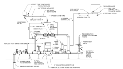
Fire pumps: NFPA 20: Standard for the Installation of Stationary Pumps for Fire Protection defines when and where pressure-regulating devices are permitted in a fire pump system. A pressure-regulating device is only permitted in the fire pump system for limited applications. However, this does not prohibit a pressure-regulating device described above in the automatic sprinkler systems and standpipe systems sections from being installed downstream of the fire pump discharge control valve.
There are two scenarios where a pressure-relief valve is required between the fire pump discharge flange and discharge check valve, including:
-
Diesel engine-drive fire pumps with a discharge pressure at 121% of the rated churn pressure exceeds the rated pressure for the system components (e.g., 175 psi). The pressure-relief valve should be set at or below the rated pressure of the system components.
-
Variable speed electric-driven or pressure limited diesel-driven fire pumps with a maximum discharge pressure at the rated churn pressure exceeds the rated pressure for the system components (e.g., 175 psi). The pressure-relief valve must be set to 10 psi above the set pressure of the pressure limiting control.
Fire pump pressure-relief valves shall be designed and installed in accordance with NFPA 20 Section 4.20 (2019 edition).

Hydraulic calculations
Careful consideration should be given to hydraulic calculations incorporating pressure-reducing valves. Calculations must be performed to assure the system pressures are satisfactory at no flow, minimum flow and maximum flow conditions. The following provides key considerations when calculating systems using pilot-operated pressure-reducing valves and nonpilot-operated pressure reducing valves.
Pilot-operated valves: Hydraulic calculations must be evaluated for each design scenario downstream of the pilot-operated pressure-reducing valve to understand the pressure available at the inlet of the pressure-reducing valve for the various design scenario flow rates.
The design scenarios resulting in valve inlet pressures below the set pressure must account for the friction loss through the pressure-reducing valve. The friction loss is manufacturer specific and dependent on the flow rate through the valve. The selected valve’s technical data must be consulted for the required friction loss.
On the other hand, the design scenarios resulting in valve inlet pressures exceeding the set pressure require the pressure loss through the valve to equal the difference between the valve inlet pressure and the set pressure. For example, if the valve inlet pressure for the design scenario is 205 psi and the valve is set to 165 psi, then the pressure loss through valve is 40 psi.
Nonpilot-operated valves: Standpipe systems using nonpilot-operated pressure reducing hose valves and control valves must be evaluated for multiple scenarios to understand the available inlet and outlet pressure for each valve in the system. There are significant pressure drops between the valve inlet and the valve outlet depending on the available inlet pressure. The pressure drop across the valve is not constant. Instead, the pressure drop varies for different design scenarios, as the valve’s inlet pressure changes.
A common application is a standpipe system employing multiple nonpilot-operated hose valves. The system must be calculated to determine the pressures required (demand) and available while the system is flowing the total system demand (e.g., 1,000 gallons per minute, or gpm) and the minimum required flow rate (e.g., 250 gpm). The hydraulic calculations must be used to determine the appropriate pressure-reducing hose valves capable of maintaining the downstream pressure at or below 175 psi for both flow rates while providing the required design flow rates and pressures.
There are unique standpipe system configurations that have nonpressure-reducing (standard) hose valves at the hydraulically most remote point of the system and pressure-reducing hose valves one to two levels below. Because the nonpilot-operated pressure-reducing valves have a significant pressure loss, the most remote hose valve may not be the most hydraulically demanding hose valve.
Therefore, standpipe system demand calculations must be performed using the most remote standard hose valve and another calculation using the most remote pressure-reducing hose valve to confirm the system’s greatest demand.
Selecting the correct device
Pressure-regulating devices are an essential component of water-based fire protection systems necessary for safeguarding system components from excess pressures. It is critical that system engineers and engineering technicians carefully select the appropriate device type best suited for each application and thoroughly understand the requirements for the design application and the device selected.
Not mentioned in this article, however equally important, is the need to test pressure-regulating devices in accordance with the applicable standards.