As large manufacturing and data center campuses continue to be built at a rapid pace, a key consideration is how to design the most appropriate fire water system to protect these facilities.
Learning objectives
- Review how to analyze the available water supply serving the fire water system and determine when on-site fire water storage is required.
- Recognize the factors for selecting the correct fire pump and fire water storage tank based on fire protection system demand.
- Understand when it is appropriate to provide redundancy in the fire water system.
Fire water system insights
- This article describes the step-by-step approach for designing campus fire water systems beginning with the initial planning stage all the way through detailed design to create the most resilient system for the facilities it serves.
- Rapid growth in data centers and advanced manufacturing demands campus-scale fire water systems designed early to ensure resilience and protection of critical assets.
- Coordinating centralized fire pumps, storage tanks and redundancy strategies during initial planning helps large or multi-building facilities meet NFPA requirements, minimize downtime and maintain reliable fire protection.
In the current era of artificial intelligence, data storage and the increased use of autonomous systems and robotics, construction of advanced manufacturing and data center facilities has grown exponentially. The race to build the fastest and most advanced systems has pushed architecture, engineering and construction to new limits.
These facilities inherently create fire hazards and challenges that require thoughtful protection solutions, while also placing an emphasis on business continuity and minimizing operational downtime. For these facilities to maximize output and capacity, it is important that early consideration be given to how the facilities and sensitive equipment areas are protected. It starts with planning at the conceptual phase for the appropriate fire water infrastructure.
Why a campus fire water system?
For typical commercial building projects, the need for fire water storage tanks and/or fire pumps is identified early in the design process. Most projects are limited to a single building where a dedicated fire pump room is coordinated to house the fire water tank and/or fire pump that exclusively serves that facility. However, where larger, multibuilding projects are being executed, consideration must be given to designing a campus fire water system.
Time, cost and redundancy are all critical factors for high-profile, large projects. By employing a central site fire water system, fire water tanks and/or fire pumps can be included in early design packages to start the procurement process and site work as soon as possible. Additionally, cost savings can be achieved both upfront and in the long term. If multiple buildings within the project scope require a fire water tank and/or fire pump, the initial cost for all the equipment and installation can be reduced.
Another savings opportunity can arise by supplying the fire hydrants across the site from the campus fire water system. This can either reduce or eliminate the infrastructure required to supply domestic water. There are also potential maintenance savings over the life of the system that can pique the client’s interest.
Finally, implementation of a central site fire water system allows for levels of redundancy to be incorporated in an efficient way. Instead of providing multiple fire water tanks and/or fire pumps per building, these can be centrally located and designed to ensure optimal performance and reliability.
Analyzing the available water supply
The first step in determining water supply capability is understanding what water source is available onsite. Depending on the location, there may be a tie-in opportunity with a municipal water supply. If so, further investigation should be performed to determine the reliability of the water supply and whether the system is dedicated for fire water or is a shared fire water/domestic water system (the latter being most common).
Reliability of the water supply must include considerations for all upstream equipment and utilities, involving factors such as municipality demand, water treatment process, pump stations, water storage tanks and configuration of the underground water main. These factors can all contribute to fluctuations that the water system may experience on a regular basis.
Once the water supply is identified, a hydrant flow test must be performed in accordance with NFPA 291: Recommended Practice for Fire Flow Testing and Marking of Hydrants. The test hydrants should be strategically selected at points where a tie-in may occur to provide the most reliable data. NFPA 291 lays out a step-by-step process and captures associated requirements to perform an accurate flow test.
Depending on the pressure drop and flow yielded by one flow hydrant, additional flow hydrants may need to be opened throughout the test. The following is a high-level summary of steps and procedures:
- Remove the cap on the residual hydrant. Open the residual hydrant to flush any potential debris. This will prevent any clogging of the pressure gauge that gets added in the next step. Then, close the hydrant.
- Attach the pressure gauge, typically 200 pounds per square inch (psi) and open the air relief valve. Open the hydrant valve slowly until it is completely open. Ensure a steady stream of water flows out of the air relief valve, then shut the air relief valve. Allow a few minutes for the pressure reading on the gauge to stabilize. The stabilized reading on the gauge represents the static pressure. Record this pressure reading.
- Remove the cap on the flow hydrant(s). Connect flow device (e.g., hose monster) to each hydrant port. Open the flow hydrant(s) one at a time. The flow hydrant(s) shall be given sufficient time to clear all debris from the stream and stabilize.
- Observe and document the flow measurements at each flow hydrant. At the same time, document the pressure reading at the residual hydrant. The reading on the residual hydrant gauge represents the residual pressure.
- After recording the pressure and flow from the residual and flow hydrant(s), slowly close the flow hydrant(s). Hydrants should be closed one at a time to prevent undue surges in the system.
- Evaluate the total flow of the flow hydrant(s) and document the pressure measured at the residual hydrant. This data point and the initial static pressure (at zero flow) are then extrapolated to create a water supply curve.
Once the data is gathered and compiled, the water supply can be graphically depicted on a N1.85 logarithmic graph. See Figure 1 green text example results.
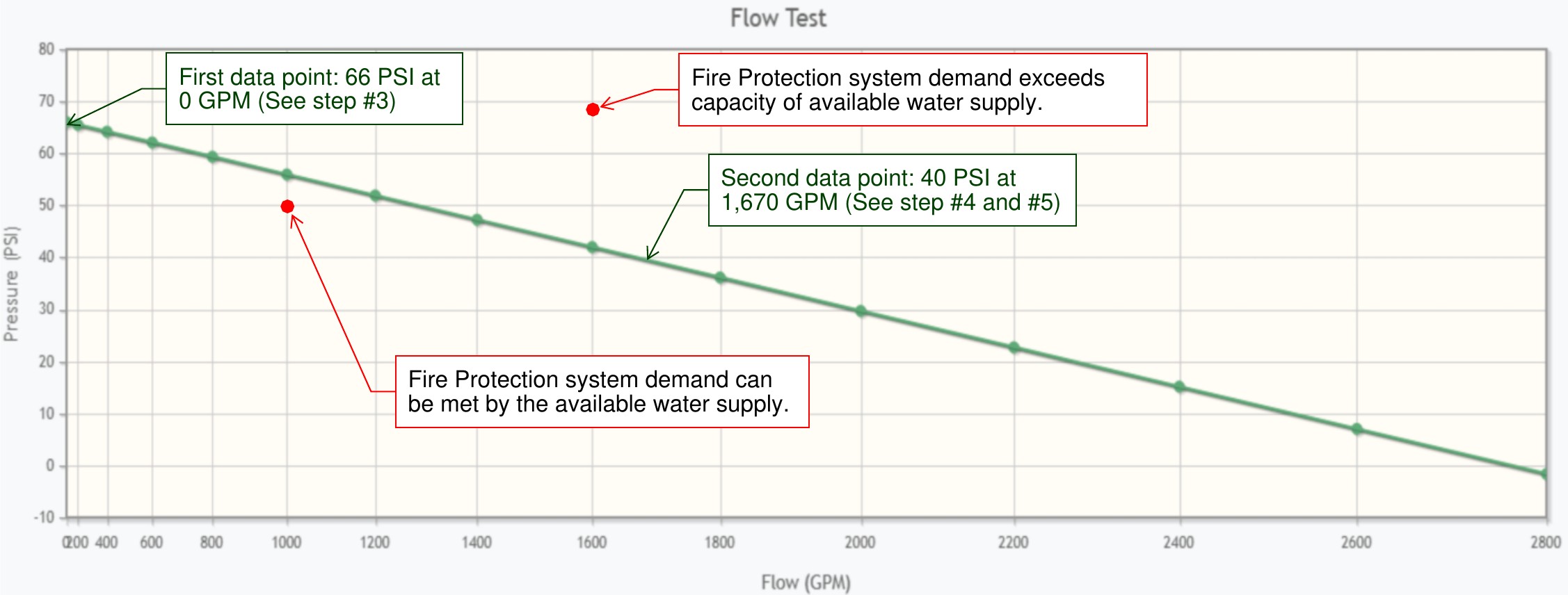
Flow test results are then used to determine if the anticipated fire protection system demands on site can be met by the available water supply. As applicable, all anticipated sprinkler system, standpipe system and fire hydrant system demands should be analyzed to determine the largest flow and pressure requirements. Depending on the facility’s occupancy, area and height, each of these may drive the fire protection system demand. Facilities with extra hazard occupancies such as energy storage systems (ESS), flammable/combustible liquids or high piled storage can drive both flow and pressure requirements.
Otherwise, fire flow provided from the hydrants typically governs the largest flow demand. Where automatic standpipes are mandated, these systems will typically drive the pressure requirement for the campus design. Preliminary calculations for each system should be compared to results obtained by the hydrant flow test to confirm those demand points fall under the water supply curve. This means the water supply is adequate. In the event the demand point lands above the water supply curve, the available supply cannot meet the fire protection system demand. See red text in Figure 1.
Fire pump selection
Sizing a fire pump starts with identifying the fire protection systems it is intended to serve. That typically includes sprinkler systems, standpipe systems and hydrants to provide fire water flow. Preliminary calculations should be performed to determine the largest flow and pressure demand of each system. It may be the case that one system type requires the greatest flow demand while another requires the greatest pressure demand.
When performing preliminary calculations, most sprinkler flow demands can be derived by multiplying the required NFPA 13: Standard for the Installation of Sprinkler Systems sprinkler density by the minimum design area, then including a 20% to 30% overage factor. Hose stream also must be included if the hydrants are located on the same supply line serving the system. Standpipe system demand requirements are outlined in NFPA 14: Standard for the Installation of Standpipe and Hose Systems and range between 500 and 1,000 gallons per minute (gpm) in sprinklered buildings.
Fire flow demand is based on the construction type of a building and building area, per the International Fire Code (IFC) and NFPA 1: Fire Code. When identifying the required fire pump’s flow capacity rating, it is important to note that NFPA 20: Standard for the Installation of Stationary Pumps for Fire Protection permits fire pumps to operate up to 150% of the pump’s rated capacity. This means that a 1,000 gpm fire pump can provide flow capacity of up to 1,500 gpm.
Next, the fire protection system pressure requirements must be considered. The most accurate calculations can be done via hydraulic models, which may or may not be possible early in design. If they cannot be performed in detail, engineering assumptions must be made after identifying the minimum remote operating pressures of each system. Assumptions include estimating the total friction loss over the pipe network and understanding the elevation changes of each system. Sprinkler system operating pressures are outlined in NFPA 13, which includes a minimum of 7 psi. If standpipe systems are present, it must be determined if they are manual- or automatic-type (most standpipes are Class I systems, assuming the building is sprinklered). The fire department is permitted to provide the pressure required for manual systems, but the fire pump must be sized to supply automatic systems.
Lastly, most jurisdictions require hydrants to provide at least 20 psi to ensure sufficient water flow during firefighting and prevent potential backflow contamination (if applicable).
Once fire pump flow and pressure ratings are identified, fire pump driver type must be selected before a final basis of design is determined. Electric- or diesel-driven are options, with electric being more common. Electric fire pumps are typically preferred due to their simpler installation, reduced maintenance and having fewer design requirements than diesel fire pumps. Power reliability plays a role, however.
It is more common that the utility does not meet the definition of “reliable” per NFPA 20 (see 9.3 and A.9.3.1(1) in 2025 edition). In this case, an alternate power source is required when power is not considered reliable. This is typically via an emergency generator. When an alternate power source is provided, the fire pump controller must be provided with an automatic transfer switch. Another option when reliable power is not available is to provide a backup fire pump in accordance with NFPA 20.
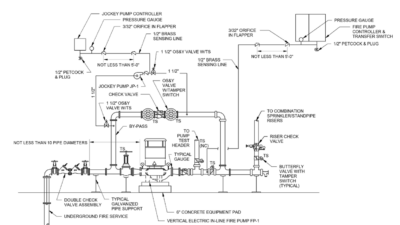
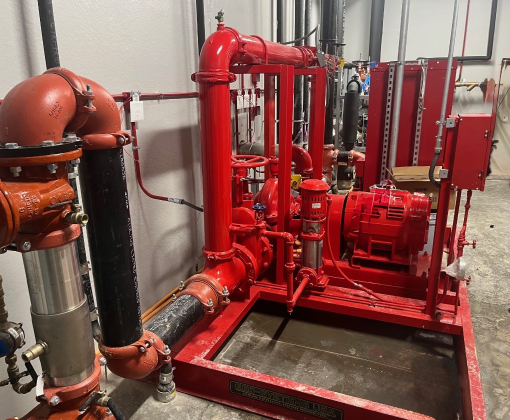
Another consideration for fire pumps is to determine if a prefabricated fire pump enclosure is preferred versus a field-installed fire pump assembly. There are many advantages to using a prefabricated fire pump enclosure. Minimal connections are required onsite and the enclosure comes equipped with all fire pump assembly components including supporting systems such as heating, ventilation and air conditioning and power. This results in a substantial reduction in the installation time required (see Figure 2).
Fire water system storage tank design
Where a municipal water supply is unavailable or inadequate, fire water storage tanks and fire pumps are required. This is generally the case for more remote locations. Design requirements for fire water storage tanks are covered in NFPA 22: Standard for Water Tanks for Private Fire Protection. This standard includes key information regarding the specification and construction requirements of the fire water storage tanks.
Permitted materials and load requirements are all included in NFPA 22. One notable criterion is the maximum permissible refill duration. Fire water storage tanks must be refilled to their minimum fire protection demand volume within eight hours. If the automatic refill rate is unable to achieve that, manual refill procedures must be implemented (typically via water trucks).
The flow rate for the largest fire protection system demand is used to size the required water volume. If the sprinkler system is the driving factor, NFPA 13 identifies duration requirements for the water supply. NFPA 14 addresses the duration required for standpipe systems. Depending on applicable codes in the jurisdiction, the IFC or NFPA 1 outlines the duration requirements associated with fire flow. Where buildings are fully sprinklered in accordance with the IFC and applicable NFPA standard, a two-hour water supply demand is typical. The total volume can then be calculated by multiplying the flow rate times the duration required.
Considerations for redundancy in the fire water system
One factor that is considered in all engineering system design is redundancy — is it appropriate and to what extent is it implemented? Fire protection system design, in general, is typically prescriptive in nature where applicable codes outline minimum requirements. Most owners prefer the simplest fire protection systems and would rather allocate their expenditures to architectural/interior design features or building systems and equipment that are used daily.
However, for mission-critical facilities where business continuity is paramount and asset protection is a priority, fire protection system redundancy should be given more attention. For these facilities that are constructed on large campuses, total project costs are typically hundreds of millions of dollars and can extend into the billions. This significant capital investment underscores the importance of mitigating downtime and designing a robust fire protection system.
The primary considerations for redundancy in campus fire water systems are based around the water supply and fire pumps. Where the municipal water supply is adequate to meet the system demand of the fire protection systems planned for the facilities, multiple tie-in points should be made to serve the campus. Designing a looped system with at least two tie-in points will both optimize hydraulic performance and provide a secondary means of supplying fire water to the site.
In the event the municipal water supply is not adequate and fire water storage tanks are required, the quantity and size of tanks need to be determined. There are two primary options: Provide a single tank that is sized for the largest fire system demand onsite or provide two tanks that are each designed for the largest fire system demand. Regarding option one, some owners prefer one tank and are willing to accept a reliable refill mechanism to replenish the tank.
On the other hand, option two provides a few key benefits that align with some clients’ risk management and insurance underwriter recommendations. The first benefit ensures that the total volume of water stored onsite is adequate for two fire events. While a fundamental assumption in fire protection engineering is that one fire event occurs at one time, this provides an additional layer of protection if two separate facilities have an event at the same time. Next, it allows for operational flexibility in meeting the NFPA 22 eight-hour refill requirement. A final benefit is that the tanks can be isolated as needed during maintenance and testing, so that there is no real downtime for the fire protection water supply.
The next redundancy-based decision is to determine how many and what kind of fire pumps should be used. As previously mentioned, reliability of the electric power utility must be assessed at the beginning of each project. Where power is not considered reliable, an alternate source of power is required. For mission-critical facilities, it is good practice to provide the alternate source of power (e.g., a generator) regardless.
By using an electric fire pump with generator backup, N+1 redundancy is provided. This is an acceptable level of risk for most owners.
However, 2N redundancy can be provided by incorporating a second fire pump, typically diesel-type, that is completely independent of the electric pump. By adding a second fire pump in parallel, the single point of failure is eliminated. This has become a popular approach in the fire protection industry to ensure complete and total operability.
Additionally, having two fire pumps allows for similar maintenance and isolation benefits to the fire water storage tanks. If one fire pump is undergoing work, there is a separate, independent pump capable of handling the entire fire protection system demand on its own.
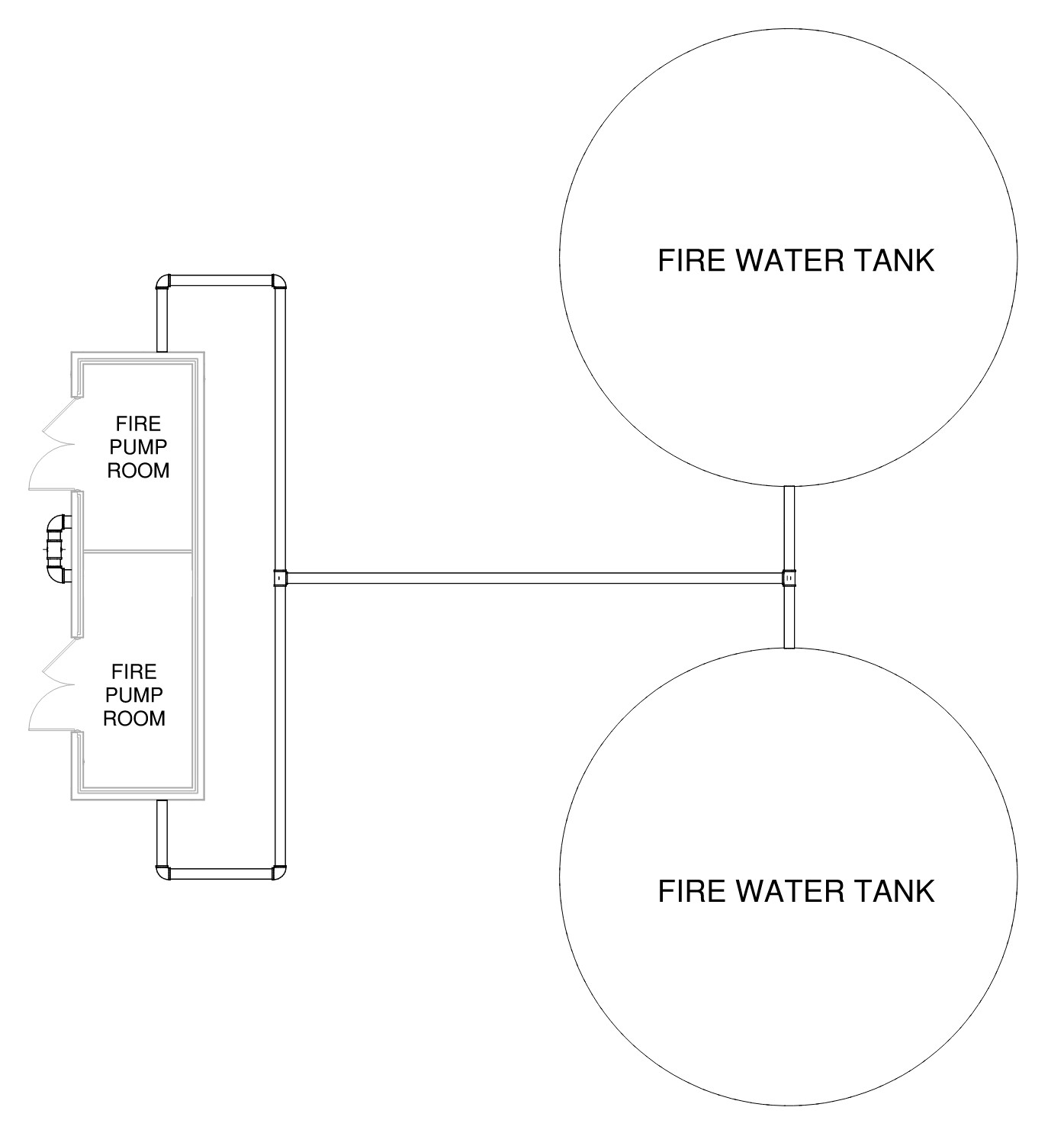
Taking these fire water tank and pump considerations into account, Figure 3 replicates a typical layout where redundant fire water storage tanks and redundant fire pumps are implemented into a design.
Campus fire water systems can help accommodate aggressive construction schedules, provide short- and long-term cost savings to the owner and incorporate redundancy that is otherwise difficult and expensive to achieve on a per-building basis. Designing for resilience has become a common theme in the architecture, engineering and construction industry and campus fire water systems can provide the reliable infrastructure required to support these mission-critical facilities.