A testing and balancing report can be a key tool for design engineers in buildings to identify issues and create quick, effective solutions
TAB insights
- TAB reports provide crucial information about HVAC system performance and discrepancies from design parameters.
- Balancing technicians play a critical role in HVAC system optimization. They require expertise in airflow dynamics, system design and the use of specialized testing equipment. Through precise measurements and analysis, technicians can adjust dampers, fans and other components to achieve desired airflow rates and temperature distribution.
![]() All design engineers at some point in their career have received a call from a client stating, “Our system is not performing as designed.” Whether that means a space is hot or cold, three pumps are running when it should only be two, system temperatures do not align with design or there are room pressurization issues.
All design engineers at some point in their career have received a call from a client stating, “Our system is not performing as designed.” Whether that means a space is hot or cold, three pumps are running when it should only be two, system temperatures do not align with design or there are room pressurization issues.
After gaining experience dealing with these types of calls, the first question is always “Do you have a copy of the testing, adjusting and balancing (TAB) report? Did you call the balancer?” The information contained within the TAB report and building control system will almost always provide the information needed to resolve the problem.
The information in the TAB is obtained from a host of different pieces of equipment that are within the balancer’s arsenal. This includes, at a minimum, the airflow capture hood, anemometer air velocity meter, hydronic manometers, infrared thermometer and additional specialty equipment for fume hood testing.

The role of technicians in balancing
The balancing technician requires expertise in airflow dynamics, system design and the use of specialized testing equipment. These professionals ensure that the heating, ventilation and air conditioning (HVAC) system operates optimally and efficiently. Key responsibilities of the technicians include:
- Measurement and analysis: Technicians accurately measure airflow rates and analyze data to identify discrepancies and areas that require adjustment.
- Adjustment and calibration: Based on the analysis, technicians adjust dampers, fans and other components to achieve the desired airflow rates and temperature distribution.
- Problem-solving: Technicians troubleshoot issues with the HVAC system and address any malfunctions or inefficiencies that may hinder proper balancing.
- Communication: Effective communication with the design team, building owners and installing mechanical contractors is necessary to understand the design intent and to report issues before completing the balancing. This will allow the technician to address any concerns.
Instrumentation
HVAC systems rely on complex instrumentation to function properly. The instrumentation includes sensors of varying types to provide inputs to the direct digital control (DDC) system, which includes, but is not limited to, air and water temperatures, air flow rate and volume, water flow and the operational status of each piece of equipment. Part of the balancing technicians work is to use several different hand-held devices that test the function of a system’s instrumentation and compare the two bits of information. The devices used by the technician must be calibrated on a regular basis to ensure accuracy.
Information obtained with the balancing technician’s devices will be used as a baseline and compared to the information from the DDC system, which is obtained from the field mounted instrumentation. Discrepancies between the two inputs must be resolved and typically the field mounted devices are re-calibrated by the DDC technician.

The report should have a section on instrumentation with a minimum of the following for each piece of equipment used:
-
A list of the test instruments that are planned to be used in the testing and balancing process. Each instrument manufacturer, model number and test application should be included.
-
A description of the testing procedure for each HVAC system. A list of all the equipment that will be tested for each system as well as the techniques to be used for the testing procedure.
-
A list of the contractors that are required to assist with the testing and balancing process along with the expectations of each of the contractors to successfully complete a total system balance. Most importantly, the expectations of the DDC technician should be described.
The basic instrumentation and methods to obtain the information include:
-
Airflow measurement devices: Central to air balancing is accurate airflow measurement. When a balancing hood cannot be used, balancing technicians use various instruments, such as anemometers, to gauge air velocity at supply, return and outdoor air intakes. Vane anemometers, favored for their versatility, use small blades that rotate by the air current to provide precise readings. A vane anemometer works on the principle that a freely spinning turbine will rotate at a speed directly proportional to the wind speed. The hand-held device will count the revolutions per minute and calculate the velocity of the air and ultimately convert to cubic feet per minute. Thermal or hot wire sensors calculate air flow based on the amount of heat removed from the surface or from the thermal resistive element with one or more temperature sensors.
-
Pressure gauges and manometers: To assess the pressure differentials between spaces and ductwork, a balancing technician will employ pressure gauges and manometers. A manometer is based on the hydrostatic balance principle, where a space or section of duct work will be connected to the reservoir so that the pressure can be measured in relationship to a neutral space. These instruments can be used to help identify potential obstructions, high loss duct fittings or imbalances within the system. The differential pressure measurements aid in adjusting dampers, registers and diffusers to achieve the desired airflow rates. Pressure gauges and a manometer can also provide room cascading pressurization maps when measured against a neutral location. Cascading room pressure control is used in laboratory and clean room design, when the room is required to be positively pressurized compared to the anti-room and then to the clean or dirty corridor.
-
Temperature and humidity sensors: Comfort is not solely dependent on airflow; temperature and humidity also play critical roles. Balancing technicians use temperature sensors, often thermocouples or resistance temperature detectors, to monitor air temperature at different points within the system. Humidity sensors, like hygrometers, help assess moisture levels and ensure the indoor environment remains conducive to human well-being and equipment functionality.
-
Balancing hoods: Balancing hoods are employed to determine the air volume supplied and returned by individual vents and diffusers. These specialized devices allow a balancing technician to measure airflows directly, enabling precise adjustments to achieve the required air distribution in each zone.
The air side balancing process for an HVAC system includes:
-
System design analysis: The first step in HVAC system balancing involves a thorough review of the design. This includes reviewing the architectural plans, equipment specifications and ductwork layout. By understanding the system’s intended design, technicians can identify potential issues that may impact airflow distribution. For example, during the design review, a balancing technician may discover issues that can hinder proper balancing, such as inadequate duct sizing or improperly located diffusers. The reviewer may discover a lack of accessibility to the equipment that could lead to the addition of access panels or equipment relocation. Identifying issues at this stage allows for early corrective measures and prevents complications later in the balancing process.
-
Airflow measurements: Accurate airflow measurements are critical for determining the existing air distribution in the HVAC system. Technicians use a variety of tools, including flow hoods, anemometers and pitot tubes, to measure airflow rates at different points within the system. Airflow measurements are taken at supply air outlets, return air inlets, diffusers, grilles and other critical locations. The data collected provides valuable insights into airflow patterns, which help identify necessary adjustment areas.
-
Equipment inspection: During the balancing process, technicians thoroughly inspect all components of the HVAC system to ensure they are in good working condition. This includes examining fans, coils, filters, dampers and other relevant parts. If any equipment is found to be malfunctioning or damaged, it is repaired or replaced by the mechanical contractor before proceeding with the balancing process. Access is key to maintaining equipment which will extend the useful life and maintain higher efficiency.
-
Adjusting dampers and registers: Closing dampers and registers will add static pressure to the system, which then reduces the airflows. However, maintaining an artificially high static pressure in a system is a waste of energy. Before adjusting the dampers, the technician should reduce the motor speed via a variable frequency drive or the speed controller on an electronically commutated motor. After the system global static is set, the dampers and registers can be adjusted to regulate the air distribution to different zones and rooms.

Understanding the TAB
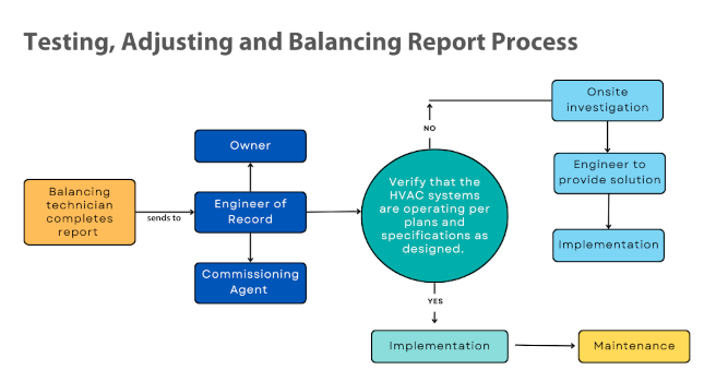
The completed certified TAB report, which typically follow National Environmental Balancing Bureau standards, is typically sent to the engineer of record, the building owner and a commissioning agent. Upon receipt of the completed testing and balancing report, the design team will review it to verify that the HVAC systems are operating as designed. There are many circumstances in which the testing and balancing reports indicate that the system did not achieve the design parameters.
It is incumbent upon the balancing technicians to provide an explanation of the issue and what corrective actions were invoked in the field to rectify the issue. If they cannot resolve the imbalance, the expectation is that the engineer of record will provide a solution. The on-site investigation typically involves the balancing technician and the system control integration specialist.
The goal is for the system testing performance data to be within the design parameters specified in the project documents (typically plus or minus percent of the design value). Large discrepancies between the design and installed systems are obvious by reviewing the TAB report and stand out as items to be corrected. The experienced reviewer will not only be looking at the information for compliance between the testing and balancing report and design documents, but also looking for the less obvious patterns to determine if there are hidden installation issues that may create system component failures in the future or limit modification/expansion of the system. This is where an experienced engineer’s review is invaluable.
Electric motors
One of the most common bits of information the engineer reviews is motor data. The reason to highlight the motor section of the testing and balancing report is that motors are a critical part of nearly every piece of equipment in an HVAC system. The reviewing engineer will look closely at the motor amperage. Motor amps are an electrical parameter representing the flow of electricity. If the current is above full load, it may be working harder than it was designed to and may point to an underlying issue. If the amperage is above the design requirements, it could be that there are increased pressure losses in the duct work or piping that were created by poor installation methods, partially blocked pipes or partially closed valves in a piping system.
Motors within systems operate on a continuous basis for 20 years or more. If the motor is operating in the service factor, it will shorten the life expectancy of the motor. In addition, as the system ages and becomes less efficient there are no means to overcome the loss. This small, but very important bit of information is the key to a design or system installation.
It is important to ask, “Was the system balanced with all the variable volume terminal units open or did the design engineer include diversity of the main air handling units (AHUs) or exhaust systems?” If there is diversity on the main systems, the balancing technician can identify a percentage of the variable air volume (VAV) terminal units to be partially closed while other units are set to max cubic feet per minute (CFM). All of the diffusers associated with the VAV must be balanced with the unit set to maximum CFM.
To give a simple example, assume the airside system is operating at 100%. When the balancing technician and the control specialist calculate the AHU supply side, the reviewer of the TAB should verify that the static pressure set point is approximately 5-10% above the last variable volume terminal unit in the system. The maximum flow requirement is when the terminal unit has the internal flow damper at 100% open. The design static pressure setpoints are a calculated value based on ideal design parameters. The installed ductwork may differ from the design due to coordination issue. The changes in ducts can add fittings or transition thus changing the design set points.
Outside air at the air handling unit
Determining the outside air values and damper controllability at the AHU is a critical component of HVAC system functionality. In many cases, however, the values provided in the TAB for the outside air, return air and mixed air temperatures are overlooked. An increase in outside air above design considerations can lead to cooling problems in summer and mixed air temperatures below freezing in winter. Airflow measuring stations on outside air dampers can be unreliable. When placed over a large damper, this is used for both minimum ventilation and airside economizer.

The percentage of outside air can be calculated from the return supply CFM and temperatures provided in the balancing report. The calculation has a higher level of accuracy than a balancing technician taking reading across the damper or the air flow station.
To obtain the outdoor air flow, the balancing technician must use test ports in the AHU, which does not provide enough space to do a profile across the entire damper or use an anemometer across several areas and take an average of readings. If an airside economizer cycle is used at the AHU, it’s recommended to install two dampers — a minimum damper and a maximum damper. The maximum damper will be used for the economizer. Air from the minimum outside air damper will be appropriately sized, which will increase the controllability and opportunity for accurate measurements of outside air.
Pre-design balance requirements for renovations
Both the design and construction industries agree on the benefits of testing and balancing all HVAC systems. The same benefits occur when requesting a pre-design balancing report for retrofit projects. The only difference is that the balancing technician only records the data and does not adjust the system. It should be noted that ASHRAE Standard 62.1: Ventilation for Acceptable Indoor Air Quality recommends a TAB audit be performed every five years to ensure efficient operation of the HVAC and control systems. Unfortunately, these 5-year audits are seldom performed. If there is an existing report, it is often from the completed project, which makes it hard to compare the existing and new reports to look for an indication of how the system aged and where the system may be failing.
Before testing an AHU, it is recommended to change filters to minimize external pressure loss. Data should be collected at each filter, noting airside coil pressured drop, outside air CFM values and mixed air temperatures. Also, a main duct pressure profile should be requested. The water side data collection includes flow rates and temperature differential at that moment in time for both the water and the air side, pre and post coil. The data will provide insight into the current performance of the system and how it uses fan or pump curves. The design engineer can plot the system curve and determine the system performance and expandability.
In addition to the data collection, this may be the right time to work with the control technician to verify the control sequence of operation for the different systems being modified.
Obtaining the system performance information before design and construction will allow the project team to understand the current state of equipment and operations, thus creating an opportunity to take corrective actions or include them in the design. The pre-balance report will help to protect the design firm from perceived errors and omissions. The proposals “assume” the existing system has the ability for increased capacity, however without test data the firm can be held accountable for a lack of system performance.