Considering total greenhouse gas emissions is becoming more important in selecting HVAC systems for low carbon building design

Learning Objectives
- Learn how energy use is converted to operational GHG emissions.
- Understand how GHG emissions from all building systems should be included to find the design with the lowest overall GHG emissions.
Emissions insights
- Incorporating total greenhouse gas emissions is crucial for selecting HVAC systems that contribute to low carbon building design.
- The transition from simple payback or lifecycle cost analysis to considering total equivalent warming impact reflects a broader industry shift towards holistic decision-making.
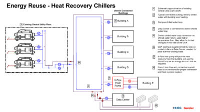
![]()
Heating, ventilation and air conditioning (HVAC) system selection has long been driven by the isolated comparison of simple payback or life-cycle cost analysis (LCCA). However, energy cost savings to recoup further investment is no longer the only consideration. Using the same logic as LCCA instead of simple payback, the refrigeration industry developed total equivalent warming impact (TEWI), which combines the greenhouse gas (GHG) emissions for the electricity to operate the equipment (indirect emissions) and the warming impact from direct refrigerant emissions (leaks, maintenance losses and end-of-life disposal losses) over the life of a piece of equipment.
Then enters embodied carbon (also known as embodied GHG emissions and is quantified in CO2 equivalent CO2e), which is the total emissions required to manufacture, transport and construct a piece of equipment or building assembly. The physical components that go into a piece of equipment require energy use, and thus GHG emissions, for them to become a useful product within a building services system. The results of a system or material Life-Cycle Assessment (LCA) to determine the environmental impact are documented in an Environmental Product Declaration (EPD) as defined ins International Organization for Standardization (ISO) 14025. There are also emissions associated with the replacement of equipment multiple times within a building’s life and maintenance in between, such as adding refrigerant and changing filters. Buildings that often have many interior renovations during their life, such as office buildings and hotels, should also consider the life and embodied carbon of finishes.

MEP and interiors embodied carbon emissions have largely been excluded from metrics and 3rd party certifications in the US, but not in other countries where EPDs documenting the embodied carbon emissions for those components are plentiful. All emissions, embodied and operational, must be included in the equation for a system to truly weigh all the pros and cons. Life-cycle carbon emissions for a building, should be the new decision-making metric for selecting all systems as part of the overall building, rather than a whole building LCA (WBLCA) that doesn’t include mechanical, electrical and plumbing (MEP) equipment or operational emissions associated with energy use and fugitive refrigerants.
Total GHG emissions calculations
In the architecture, engineering and construction (AEC) industry, calculation of building embodied carbon via WBLCA has only begun in recent years and is still not common place for all projects. Before recently, calculation has been largely focused on structural and enclosure components. MEP components have often been excluded, partially because there have been no product-level LCAs performed to produce the data for EPDs to include in analysis. Industry groups, like MEP 2040, have been working to push manufacturers to perform product-level LCAs on their equipment so it can be included. Until EPDs are available, the CIBSE TM65 standard has been used to estimate the embodied carbon associated with MEP equipment based on its constituent materials.
MEP system embodied carbon data must be available either via TM65 or EPDs to include the emissions associated with the production and installation of a system. This includes all the emissions associated with a system in the analysis, while also weighing avoided operational emissions associated with lower energy use against the emissions cost of producing the equipment and the required components.
Many system types that are associated with high-performance or lower energy use require more sub-components. For example, active chilled beams result in less duct work and energy use, but more copper and aluminum for distributed coils in each zone, along with piping to connect chilled and hot water. Could the piping material be changed to reduce the overall emissions impact of the system? However, if there’s no reliable data for all the system components, an accurate analysis to ensure the lowest emission system has been selected can’t be completed.
Comparing MEP systems based on their energy use and first cost is standard practice. GHG emissions need to be looked at when weighing the energy use with the embodied carbon. Electricity use (scope 2, indirect emissions) can be converted to equivalent GHG emissions using electricity grid emission factors. These grid emission factors are created using the types of electricity generation and the associated GHG emissions for each grid region.
The most commonly used emissions factors are from the U.S. Environmental Protection Agency Emissions & Generation Resource Integrated Database (eGRID). eGRID emissions data includes emissions from carbon dioxide (CO2), nitrogen oxides, sulfur dioxide, mercury, methane (CH4), nitrous oxide (N2O), and carbon dioxide equivalent (CO2e). CO2, CH4 and N2O are greenhouse gases that contribute to global warming. The data and resulting eGRID emissions factors are updated annually to provide the average emissions per kilowatt-hour used in that year. ASHRAE 228-2023: Standard Method of Evaluating Zero Net Energy and Zero Net Carbon Building Performance includes eGRID emissions factors for calculating source energy emissions. The drawback of using eGRID factors is that they look at the past, which isn’t ideal when used for comparisons to a building that will go into service two-five years in the future. Make sure to research any available plans for grid emission reductions by the electricity generating utility.

Annual average emissions factors also don’t allow designers to optimize building energy use based on when during a given day whether cleaner or dirtier energy is being provided to the grid. Hourly emissions factors can be used to quantify these effects, which is especially important when quantifying demand peak shifting systems, like thermal energy storage and batteries. There are also marginal, hourly emissions factors, which are more appropriate for use in comparison decisions that would result in more electricity capacity requirements for the grid. This is because they include the emissions impact of having to potentially dispatch another power plant to meet the demand changing the source energy mix.
Marginal emissions factors are further divided into short-run (SRMEF) and long-run (LRMEF) types. LRMEF accounts for demand changes in the operation and structure of the grid. LRMEF are typically lower than SRMEF. LRMEF are more forward looking to account for the reduction in grid emissions. The National Renewable Energy Laboratory Cambium tool is the most common source of this forecast data in the United States. The first public comment draft of ASHRAE 240P: Quantification of Life Cycle Greenhouse Gas Emissions of Buildings includes future emissions factors from Cambium for use in the calculation of life-cycle GHG emissions.
Refrigerant emissions
Another source of carbon emissions comes from fugitive refrigerants. The impact of refrigerants on MEP operational GHG emissions has been largely ignored until recently. Commercial refrigeration has included their impact in TEWI evaluations, which could also be employed for HVAC. To complete the puzzle of a true, whole building LCA, the GHG emissions from fugitive refrigerants must be included. The Montreal Protocol and the Kigali Amendment, have already created regulatory requirements to reduce the global warming potential (GWP) of refrigerants. The U.S. is currently transitioning from hydrofluorocarbon (HFC) refrigerants to hydrofluoroolefin (HFO) refrigerants with GWPs less than 700 kg/kg CO2e for most HVAC equipment types. This transition will reduce the emissions associated with fugitive refrigerants, but some HVAC systems still require higher refrigerant charge per ton of cooling. Equipment with larger amounts of field installed piping and charge can also result in greater emissions via leakage.

The total GHG emissions associated with the fugitive refrigerant must be included to capture all the emissions associated with system selection. Studies have shown that fugitive refrigerant emissions are on the order of 50% of embodied carbon for the building structure/enclosure and 15% of 60-year building life operational emissions. Higher charge systems with greater potential for leaks will result in even higher amounts of fugitive refrigerant emissions. To estimate fugitive refrigerant impacts, MEP 2040 has created an online refrigerant impact tool, which includes multiple dataset choices for emission rates, leakage rates, and equipment types. ASHRAE 228 requires fugitive emissions to be included and provides a table of emission rates per equipment type based on a 2015 French study of field maintenance data..
HVAC system sizing
HVAC system right-sizing has long been an approach used by designers to optimize buildings for energy use and cost. Right-sizing also has an interactive effect on the embodied carbon and the true, life-cycle carbon emissions for a building. It pulls on the first cost, operational energy (cost and emissions) as well as the embodied carbon. It is well established that right-sized systems operate more efficiently and cost less than over-sized systems.
A right-sized HVAC system has less copper, smaller duct work, less piping, smaller electrical conductors and gear and lower refrigerant charges, all of which result in lower embodied carbon. The classic example of bringing embodied carbon into MEP system sizing is the effect envelope performance has on MEP system size. If the emissions associated with the embodied carbon of the MEP system, envelope and energy use are not included in the analysis, it is not possible to know whether increasing envelope insulation while reducing HVAC system size actually reduces total emissions.
By using GHG emissions, the AEC industry has a new framework for decision making that connects aspects of building design that were once thought of only as separate systems. The industry must adapt to using a true, whole building LCA approach for making holistic decisions for low carbon building design and operations.