This mass notification and emergency communication system design discussion is holistic and includes all associated coordination requirements.
Learning Objectives
- Learn about the systems that comprise fire alarm and mass notification system components.
- Understand occupant-notification requirements.
- Increase understanding of speech intelligibility requirements.
Modern fire alarm detection and notification systems perform many technical roles while operating in the background, usually innocuous and passive. But these systems are responsible for life-saving duties, including smoke control, building evacuation, or defend-in-place messages, and alerting mass notification events.
The technology is constantly evolving, and the codes that dictate the use of these systems evolve as well. Upgrading legacy systems to modern equipment that comply with the most recent codes is a challenge for both facilities and engineers.
The International Building Code (IBC) contains requirements for fire alarm systems based on how the building will be used, called the occupancy type. Section 907 of the 2018 IBC includes fire alarm system requirements for the occupancy groups listed within the IBC. The NFPA 72: National Fire Alarm and Signaling Code defines the requirements for implementing fire alarm systems.
The simple way to understand the differences between these documents is that IBC determines what fire alarm components are required and NFPA determines how they are to be implemented. Additional requirements exist in codes adopted by municipalities, states, and federal agencies. For example, the Unified Facilities Criteria (UFC), Section 4-021-01, may be required on government projects for the U.S. Air Force, Army, Marine Corps, Coast Guard, or Navy.
Fire alarm control units
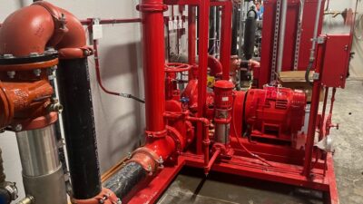
At the heart of any fire alarm or mass notification system is the head-end, or the brain. Modern systems use a central processing unit (CPU) housed in what is referred to as a fire alarm control unit (FACU) in NFPA 72. The FACU is a specialized panel that provides system status, system control, and battery backup and receives signals from initiation devices and then outputs signals to notification and auxiliary devices (see Figure 1).
A small building is likely to have one FACU, to which all devices connect. A large building or campus will have many FACUs, extender panels, or expansion panels. Expansion panels, sometimes called transponder panels, do not contain the CPU but offer the same connectivity as a FACU. Large systems require connectivity between panels to facilitate communication of alarm events and status.
It is important for communication to be maintained at all times, so a loop-based topology is important to strive for. The benefit of a communication loop is that a wiring failure (due to physical damage of wiring) can be identified without loss of communication. This reliability is especially important for voice notification and mass notification systems.
Initiation devices
An initiation device is one that tells the fire alarm system that an event has occurred. Initiation devices include smoke detectors, heat detectors, manual pull stations, and interface modules. In the IBC, each occupancy has requirements for the placement of manual pull stations, which includes building exits, at building separations (where two separate buildings connect), within the building at stair entrances, and additional interior locations based on travel distances. One way to consider placement of manual pull stations is that you want the device located in the path of exit travel, typically as a last action before leaving the floor or building.
Smoke-detection requirements will also vary based on occupancy type and are commonly required in exit passageways (also called egress pathways). It is important to protect egress pathways so occupants can exit a building safely. Smoke control requirements are based on this same premise, protecting paths to the exits.
Heat detection is another form of initiation device that is suitable for locations that are susceptible to dust. Nuisance alarms from smoke detectors in mechanical rooms and unfinished spaces tend to push owners toward heat detectors. The temperature ratings of heat detectors can be rate-of-rise or fixed temperature, and the ambient temperature conditions of the space must be taken into consideration. The heat detector will initiate before a nearby sprinkler head, providing early warning and the exact room the condition occurred.
Interface modules are wired to electrical contacts and monitor the status of those contacts. These modules can be used to monitor any dry contact but are commonly wired to sprinkler system flow switches, valve tamper switches, exterior enclosures for fire department key access, air-sampling smoke-detection systems, “beam detectors,” fire-imaging camera systems, power monitoring of fire alarm-related electric circuits, and generator status.
These inputs may not be programmed for building alarms but may instead provide supervisory or trouble indications. Historically, interface modules have also been used to monitor security buttons or other non-fire alarm statuses, but facilities are moving away from that approach with the ability to use modern technology systems and cleanup fire alarm wiring.
Auxiliary devices
An auxiliary device is one that changes the state of a contact (either normally open or normally closed) when fire alarm programming determines an action is to take place. These devices can be used to provide power to components or systems, provide signals to other systems, or activate components or systems. Because the auxiliary device is simply a contact closure, the device can control one component or several.
One common application is the activation of smoke or fire/smoke dampers in HVAC systems (see Figure 2). A duct smoke detector samples the air for the presence of smoke in an HVAC duct near the location of a damper. The initiation device signals the FACU and programming causes an auxiliary device to remove power from the damper, allowing it to close. In some facilities, the procedure may be to close multiple dampers on the floor and to shut down the corresponding HVAC unit and close all dampers associated with that HVAC unit. A common challenge in facilities is knowing the location of every auxiliary device, a challenge that can be made easier when locations are not hidden from view or use a location ID on a nearby ceiling or wall.
A notification appliance notifies occupants of an alarm event. These appliances include visual notification in the form of strobes and audible notification in the form of horns, chimes, or speakers. The best way to think about visual notification is to think about the need to notify occupants that are hard of hearing, deaf, or wearing hearing protection. These occupants rely solely on visual cues (tactile cues aren’t adopted methods) for being notified of a building condition.
For this reason, NFPA 72 has specific requirements for the light intensity (measured in candelas) of visual devices. The simple way to approach visual notification is to think about how to get the attention of occupants given the tasks that will be performed in that space (see Figure 3). When walking down a corridor, the visual range of building occupants is toward the direction of travel, which is partly why NFPA allows for lower-intensity levels for corridor devices.
Additional requirements are based on the area of coverage and increase intensity for the purpose of getting the attention of the occupants when their tasks direct their focus away from visual device locations. In spaces that have highly involved tasks in and around equipment, such as mechanical rooms and electrical rooms, notification appliances should have higher output levels to overcome the focus and physical barriers that pertain to the tasks at hand.
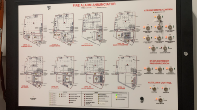
When commissioning fire alarm visual notification systems, the candela output setting should be verified. This setting may be physically selected at the device, in which a label will usually be visible, or the setting can be determined by the FACU. In the case of the latter, a printout with a floor plan should be available to verify device settings.
Because candela outputs directly relate to required energy, thus battery usage, it is important to spend the necessary time both during design and shop-drawing review to verify battery calculations are based on the required candela levels. If the commissioning or field-verification process is increasing the candela output of multiple devices, a recheck of voltage drop and battery calculations would be recommended. Fire alarm systems should have less than 80% loading of a battery system (per UL 864: Standard for Control Units and Accessories for Fire Alarm Systems and other governing documents), and this spare capacity should be maintained after commissioning.
Acoustics
The most challenging part of fire alarm notification design is developing audible coverage because proper design requires an understanding of building acoustics. The traditional audible-notification method used bells, which was later updated to electric horns or chimes. These methods benefit from acoustic reflections that increase the usable signal level because horns and chimes produce noises that do not have intelligibility requirements. NFPA 72-2016 18.4.3.1 identifies the minimum audible-signal level required, which is “15 dB above the average ambient sound level or 5 dB above the maximum sound level having a duration of at least 60 seconds, whichever is greater.”
Just as visual devices have candela outputs that get the attention of occupants, audible devices achieve the same goal through decibel levels and frequency response. Some horns have adjustable output settings, as do some chime devices. Designers must coordinate the device layout with the output level chosen because reducing output during commissioning may result in the need to add devices.
Additionally, audible devices require energy and affect battery usage; getting the battery calculations correct requires an accurate count of every device and its wattage setting.
Audible devices need to be evaluated for their ability to be audible through closed doors (assuming the doors aren’t designed for acoustic isolation). The sound transmission class (STC) of a typical door is around STC 10, which is approximately 10 dB of transmission loss around 1 kHz. A typical wall or partition can be expected to have an STC of 30 or more. It is reasonable to calculate attenuation loss through one non-acoustic door. It is not reasonable to expect audible devices to provide required coverage through walls or multiple rooms/doors.
Another factor to consider is attenuation over distance. Some design guides may use a free-field attenuation of 6 dB per doubling of distance for calculations inside a building. Actual attenuation over distance inside occupied buildings is not accurately modeled using free-field calculations. One method published in ASHRAE Transactions, 1985, volume 91, pt. 1A presents an equation developed in ASHRAE Research “Project Report RP-339.” The resulting equation, sometimes referred to as the Shultz equation, was developed using a curve-fit to a series of measurements. The intent was to characterize sound propagation inside a typical room, and this equation is referenced in ASHRAE Handbook, HVAC Applications, Chapter 48: Noise and Vibration Control, Equation 26 to predict HVAC noise levels from ceiling diffusers in normally finished rooms.
Because the equation was based on a series of measurements, an application would need to closely mimic the original measurements to be accurate. Designers want to be realistically conservative in these calculations, and it is better to err on the side of being slightly louder than needed.
Software is available that can more accurately model room acoustics, and programs are specifically designed to perform fire alarm notification calculations. NFPA 72 requires that designers review acoustically distinguishable spaces (ADS) and perform calculations for a representative of each. This is to say that the designer can perform an acoustic calculation on a typical room, then apply that concept to rooms with similar size, purpose, and acoustical finishes. Rooms or spaces with unique attributes should be calculated separately.
Voice communications and intelligibility
More recently, many building types are either required to, or choose to, use speakers to allow for voice communications. Voice systems add an audio amplifier and voice-capable head-end to the FACU. These systems require the ability for the system to transmit either preprogrammed voice messages or live messages throughout the building or campus.
NFPA and other governing agencies have specific requirements for speech intelligibility, which may be measured as speech transmission index, rapid speech transmission index, speech intelligibility index, articulation index, or common intelligibility scale. These systems provide a single number score, with higher scores indicating higher intelligibility performance.
One key component to take into consideration is that while acoustic reflections helped usable levels of horns and chimes, acoustic reflections can hurt intelligibility. The most intelligible signal is only heard once and is heard with a frequency response that matches the original signal. Reflections that occur more than 10 milliseconds after the original signal are perceived as a second signal and sound like an echo.
Reflections also affect the frequency response observed by causing phase interference (both constructive and destructive). This is to say that some frequencies are out-of-phase and cancel, and others are in-phase and add.
A change in frequency response can affect intelligibility. The transmission loss of doors, while able to be overcome with horns and chimes, negatively impacts speech transmission to an extent that intelligibility cannot be expected.
Another factor to consider is background noise. The requirements for background noise are more stringent for voice systems than horns or bells because of the negative impact that noise has on speech intelligibility. The sound produced by a typical HVAC system is similar to the noise used in speech-masking systems, which are speaker systems that are designed to make it difficult to understand what is being said elsewhere in the room. For this reason, NFPA requires voice systems to meet intelligibility requirements in addition to overall decibel levels. Speakers have adjustable output levels, sometimes called taps, and the settings are based on the wattage used by the speaker. Typical settings are ¼ W, ½ W, 1 W, and 2 W. Every doubling in wattage is an increase in 3 dB of sound power level or 6 dB of sound pressure level.
Speaker location is important and the traditional locations for horns or chimes are usually not viable for speakers. There are several reasons why:
- Intelligibility is helped by using multiple speakers at lower output levels as compared with fewer speakers at higher output levels. This correlation is due to how room reverberation affects intelligibility.
- For a speaker to be intelligible, the listener needs to be in the direct field of the speaker, which means most of the sound heard is direct from speaker to ears rather than reflected off walls or other surfaces.
- Many horns or chimes are located on a wall and less commonly located in ceilings.
Optimal speech intelligibility usually occurs using arrays of ceiling speakers; wall locations can be problematic when multiple speakers are used. Wall speakers can be successful if most of the area is covered by a single speaker so that phase interference due to multiple arrival times is minimized. For larger areas, corridors, or reverberant spaces, an array of ceiling speakers is usually the most successful approach. Speaker spacing can follow typical paging-speaker layouts based on edge-to-edge, minimum-overlap, or center-to-center methods. In general, it is helpful to lay out the system so occupants hear one speaker at a time, and when overlap exists, the arrival times are nearly equal.
Commissioning and verification of audible notification systems includes sound pressure-level verification for horn or chime systems but is more involved for voice systems. A voice system should be tested for both level and speech intelligibility within the required ADS. The method for speech intelligibility is defined in NFPA 72 and consists of using a “talkbox,” which is a speaker placed in front of the microphone in the FACU.
This test represents the intelligibly of the entire system, both electric and acoustic, and can be adversely affected by high background noise at the FACU location. Just as NFPA 72 defines ADS for design goals, field verification can be limited to a representative ADS. NFPA 72 does allow for accurate computer simulations to take the place of some field measurements so long that the installed condition closely matches the modeled condition.