Operating rooms, for years, have been designed by older standards to a room temperature and don't adapt well to the current standards, which means hospitals have to adjust dehumidification requirements.
This past year, a local regional hospital our company often works for asked us to retest an existing desiccant dehumidification unit supplying outside air to their surgery unit. The hospital had been having problems maintaining humidity levels in the area below 60% and they suspected the process air and regen air to be too high, causing these issues. The unit was originally installed in 2010.
Operating rooms, for years, have been designed by older standards to a room temperature of 68-73°F and 30 to 60% relative humidity. Surgeons today are desiring their operating rooms be maintained at 60-65°F or lower due to longer procedures with newer technology and wearing heavy multiple-layer gowning. The desired lower temperatures still require room-relative humidity to remain at 50%. These lower room temperatures and humidity are very difficult to achieve with conventional HVAC chilled water and direct expansion type systems. Desiccant dehumidification units have been added to pre-condition the outdoor ventilation air prior to the main surgery air handling unit (AHU). By removing the moisture load, the main surgery AHU coil can achieve the lower room temperatures.
A few years prior, a sister hospital was having similar issues with their desiccant outside air unit. The sister hospital had determined that the desiccant wheel had become saturated with moisture after the wheel rotation motor had failed, so the wheel had not rotated for some time. The problem was not resolved even after replacing the rotation motor (Diagram). The saturated wheel had lost its effectiveness to remove moisture. The sister hospital replaced the desiccant wheel and the problem was solved. Our local regional hospital decided to replace their desiccant wheel but had no improvement to humidity conditions.
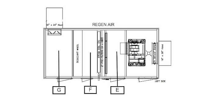
The hospital called us onsite to meet the desiccant wheel rep, the engineer, and hospital maintenance to investigate, and bring the unit back to design performance. Design performance from the submittal is shown in the table and Figure 1.
Courtesy: AABC/Systems Analysis Inc.[/caption]
The desiccant wheel manufacturer’s representative suggested using the pressure drop across the wheel to calculate the airflow of the regen air. This is the method they use at the factory to test airflow prior to shipping. The process air measured pressure drop matched the submittal at 0.72 in. water gauge (w.g.) and confirmed the duct traverse at 4,000 CFM. The regen air pressure drop measured 0.28 in. w.g. Per the submittal, the pressure drop should be 0.55 in. w.g. At design flow, the in. w.g. calculated to 1,800 CFM, confirming the regen airflow was, in fact, low. The hospital admitted they had changed the motor and fan sheaves a few months before to increase the regen temperature by decreasing the suspected high regen airflow.
The original sheaves were found and replaced. The wheel pressure drop was retested and now confirmed back up to 0.55 in. w.g. The regen airflow now confirmed at 2,500 CFM. The regen temperature was still only 188°F versus a design of 213°F and not taking the moisture off the new desiccant wheel. The steam control valve was removed and found to be only partially opening. The steam control valve was replaced and 220°F was achieved. The process air was now operating and testing as designed. The operating rooms quickly recovered by recording room conditions of 62°F at 50% humidity.
Reflecting back on the steps taken to get the desiccant dehumidification unit back to design conditions; the problem seemed to be the steam valve not being able to produce the heat temperature of 213°F needed to remove the moisture from the wheel. The wheel may not have needed to be replaced. The sheaves should not have been changed from the original set. Using the pressure drop across the wheel, in this case, proved to be the best method of determining the actual airflow for the regen air path.
When troubleshooting a problem unit, it is necessary to investigate the entire system and all components to get to the root of the problem.
This article originally appeared on the Associated Air Balance Council (AABC) TAB Journal. AABC is a CFE Media content partner.