This provided a general overview of low-voltage switchgear and switchboards, including definitions, standards, advantages and disadvantages

While switchgear and switchboards are similar — they’re distribution equipment, they contain overcurrent protection devices and they often serve as service![]() entrance equipment — they also have important differences between them. Electrical engineers often have a vague understanding of their differences and applications. Questions range from the general, “What is the difference between the two?” to the project-specific, “Which should I use here?”
entrance equipment — they also have important differences between them. Electrical engineers often have a vague understanding of their differences and applications. Questions range from the general, “What is the difference between the two?” to the project-specific, “Which should I use here?”
This article will focus on low-voltage switchgear and switchboards. Medium-voltage distribution equipment is a complex subject, warranting its own article and is not addressed here.
This will also focus only on the American National Standards Institute, UL, National Electrical Manufacturers Association and/or IEEE circuit breaker standards, not the International Electrotechnical Commission (IEC) or other standards uncommon in North America.
For a general overview of switchgear, refer to an article in July 2020 Consulting-Specifying Engineer by Tom Divine: “Back to basics: Switchgear, transformers and UPSs.”
Electrical system overview
The requirements in NFPA 70: National Electrical Code for switchgear and switchboards are nearly identical whether discussing working clearance requirements, grounding/bonding requirements, arc energy reduction, egress requirements and other installation requirements.
The major differences in the application of the two types of units are primarily based upon in how they are constructed and how that construction meets the design goals and limitations. Table 1 provides a brief comparison of switchgear and switchboards.

The term “switchgear” is defined by NEC Article 100 as:
“An assembly completely enclosed on all sides and top with sheet metal (except for ventilating openings and inspection windows) and containing primary power circuit switching, interrupting devices or both, with buses and connections. The assembly may include control and auxiliary devices. Access to the interior of the enclosure is provided by doors, removable covers or both.”
Switchgear can be designed in a variety of configurations, thereby offering improved reliability and maintainability when compared to a switchboard.

The term “switchboard” is defined by NEC Article 100 as:
“A large single panel, frame or assembly of panels on which are mounted on the face, back or both, switches, overcurrent and other protective devices, buses and usually instruments. These assemblies are generally accessible from the rear as well as from the front and are not intended to be installed in cabinets.”
Switchboards are generally simpler in construction than switchgear, offering less reliability and maintainability, but at the benefit of lowered costs. Switchboards may also be built to include panelboards and transfer switches, while switchgear cannot. In contrast to the NEC definition, modern switchboards often do not require rear access. Most differences between switchgear and switchboard are described in industry standards detailed in the next section.

Electrical system standards, industry guides
While the UL, ANSI and NEMA standards that define the construction and testing of switchgear and switchboards are generally covered by standard specifications during the design process and, therefore sometimes ignored or taken for granted by design engineers, they are the foundation needed to understand the differences and significance of those differences between the two types of equipment.
Switchgear type construction is evaluated against the following standards and guides:
- UL 1558 — Standard for Metal-Enclosed Low-Voltage Power Circuit Breaker Switchgear.
- ANSI/IEEE C37.20.1 — Standard for Metal-Enclosed Low-Voltage power Circuit Breaker Switchgear.
- ANSI C37.51 — Metal-Enclosed Low-Voltage AC Power Circuit Breaker Switchgear Assemblies — Conformance Test Procedures.
Switchboard type construction is evaluated against the following standards and guides:
- UL 891 — Standard for Switchboards.
- NEMA PB 2 — Deadfront Distribution Switchboards.
Low-voltage circuit breakers are evaluated against the following standards and guides:
- UL 489 — Molded-Case Circuit Breakers, Molded-Case Switches and Circuit-Circuit Breaker Enclosures.
- UL 1066 — Standard for Low-Voltage AC and DC Power Circuit Breakers Used in Enclosures.
Low-voltage circuit breakers
Low-voltage circuit breakers come in a variety of types and sizes with a wide array of purposes and applications. For this article, we will be focusing on the types of circuit breakers defined by UL 489 and UL 1066.
UL 1066 includes low-voltage power circuit breakers, often also referred to as air, steel-frame or iron-frame circuit breakers. Low-voltage power circuit breakers are commonly designed with a focus on maintenance. The circuit breakers are almost always drawout-type to allow easy serviceability, the circuit breakers and appurtenances are not enclosed in an overall case that cannot be removed and individual parts may be replaced as necessary.
UL 1066 circuit breaker overcurrent protection control is provided by trip units that may generally be selected to provide various ranges and types of long-time, short-time, instantaneous and ground protection.
UL 489 lists low-voltage molded-case circuit breakers, which includes both regular molded-case circuit breakers and insulated-case circuit breakers. Molded-case circuit breakers are defined as “a circuit breaker that is assembled as an integral unit in a supportive and enclosed housing of insulating material.”
Essentially, all parts are contained within an overall enclosure. Molded-case circuit breakers may be designed with thermal-magnetic or solid-state/electronic trip units. While some molded-case circuit breakers are capable of some level of disassembly, most are not. If the device is malfunctioning or otherwise damaged, it normally has to be replaced in its entirety.

Insulated-case circuit breakers are a subset of molded-case circuit breakers that do not have a formal definition but are generally understood to include some form of a charging or two-stage action for storing mechanical energy to quickly open. In many ways, insulated-case circuit breakers are a hybrid of both molded-case and low-voltage power circuit breakers, having functionality similar to the power circuit breaker but in the configuration of the molded-case type.
An important distinction between UL 1066 and UL 489 listed circuit breakers beyond their styles of construction is their overcurrent protective functions. UL 489 circuit breakers will always have instantaneous trip functionality that is usually adjustable. UL 1066 circuit breakers will commonly — but not always — have instantaneous trip functionality.
Even when UL 1066 circuit breakers have instantaneous trip functions, they may sometimes be capable of being disabled or otherwise turned off through settings adjustments. We will discuss how this ability to disable instantaneous protection may seriously impact the protection of UL 891 switchboards.
Switchgear and switchboards: construction
Switchboards are often constructed with overcurrent protective devices, metering equipment and other appurtenances in grouped sections such that the devices are not isolated from one other. It should be noted that some switchboards can be constructed with individual isolated sections in a similar vein to switchgear, but such examples are rare. When discussing switchboards in this article, we will be referring to the constructions with group-mounted devices. While the metaphor should only be taken so far, a one-section switchboard can basically be thought of as a very large sibling to a panelboard.
Switchboards may be equipped with either UL 489 or UL 1066 listed circuit breakers, as well as fused switches. When equipped with UL 1066 listed circuit breakers, special care must be given to ensure the switchboard is properly protected from short-circuit conditions.
UL 1558 listed switchgear are rated to withstand short-circuit currents for four cycles with short-time ratings of either 30 or 60 cycles The four-cycle short-circuit interrupting capacity of the circuit breaker is the maximum fault the circuit breaker is capable of interrupting, while the 30- or 60-cycle short-time rating of the circuit breaker is a current of lower magnitude that the circuit breaker can withstand for a longer period of time.
For instance, a circuit breaker might be rated to interrupt a 100 kiloamperes fault current for up to four cycles and withstand a 65 kA fault current for up to 30 cycles. UL 891 switchboards are rated to withstand short-circuit currents for three cycles with no short-time ratings.
This distinction, especially in relation to the short-time ratings, is significant as the switchboard must be protected from higher magnitude faults that persist for three cycles or longer. As discussed above, UL 1066 circuit breakers may have their instantaneous trip function disabled. If the fault current to which that switchboard may be exposed is less than the maximum instantaneous pickup of the UL 1066 circuit breaker protecting the switchboard without instantaneous protection, the switchboard may fail.
Switchgear is constructed of individual sections of circuit breakers, relays, fuses, metering equipment and other appurtenances and compartmentalized by a complete metal barrier that isolates adjacent vertical sections from one another. Bus bars for each phase, neutral and ground extend horizontally throughout the entire switchgear assembly and connect to each individual vertical bus bar in each section. The vertical busbars in these sections will connect to feeder power circuit breakers to distribute power to downstream systems.
Switchgear are designed to use draw-out type circuit breakers, which allow for easy removal and reconnection to the switchgear bus. Only UL 1066 listed power circuit breakers may be used in UL 1558 switchgear. Switchgear circuit breaker frame ratings typically range from 800 A to 6,000 A, depending on the manufacturer of the switchgear. The draw-out design allows for ease of maintenance in and helps avoid unnecessary de-energization of other downstream systems connected to the switchgear bus.

Switchgear and switchboards: options and applications
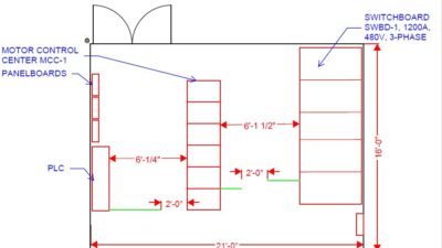
Switchgear are generally the largest pieces of electrical equipment in an electrical room. When sizing electrical rooms, it is important to consider that most switchgear will require both front and rear access. Also, with the draw-out design of the circuit breakers, engineers must account for both NEC-required working space clearances as well as the space required for drawing the breaker out and any breaker lifting devices required to remove and replace the breakers from their sections.
The length of switchgear can also widely vary depending on the complexity of the switchgear design and quantity of circuit breakers, which both increase the quantity of total individual sections required. Switchgear commonly have depths of at least 60 inches, with depths of 72 inches or even 90 inches not uncommon.
Front-access only switchgear may have depths as low as 40 inches, however, these often require an extra cable section adjacent to each circuit breaker section, potentially doubling the width of the gear.
A major application advantage of switchgear is the incorporation of advanced controls — either through relay logic, programmable logic controller-type intelligent controls or a combination of the two. A common configuration of switchgear is a “main-tie-main” where the tie circuit breaker will typically be “open” and with each main circuit breaker “closed” to provide power to each independent bus section of the switchgear.
This is often referred to as “dual-ended” switchgear because the switchgear will often have two separate sources of power. If there is a loss of power on one of the sources or a fault that trips one of the main circuit breakers or requires maintenance, the circuit breaker will trip and disconnect power from that respective section. The controls of the switchgear will “close” the tie circuit breaker to allow power to be restored to the interrupted section.
Switchgear may also incorporate intelligent relays into their protection schemes. Such relays monitor voltage, current, frequency and other power quality parameters to observe the electrical system and detect potential faults or other abnormal scenarios far beyond the capability of the more modest basic overcurrent circuit breakers. Switchboards, lacking sectionalized compartments, generally do not have the means to include relays or similar intelligent controls.
Switchboards are generally smaller than switchgear and may also require substantial space, especially if transfer equipment, panelboards or similar equipment are included in the lineup. Some switchboards may be constructed with UL 1066 draw-out circuit breakers, which engineers must account for in the same manner as for switchgear.
One major advantage of switchboards is the wide array of circuit breakers that may be installed. A single switchboard section may contain circuit breakers ranging from as low as 20 A to as much as 1,200 A or more depending on the manufacturer. Switchboards may come in a variety of depths, from as little as 24 inches to as much as 60 inches, with 36 inches being quite common.
In terms of pure functionality, while switchboards may incorporate an automatic transfer switch, panelboards and other equipment into their enclosures, switchgear may incorporate transfer schemes and control of significantly greater depth making them ideal for more complex electrical systems.
Front- and rear-access can add substantial space to the proposed layout of an electrical room — or preclude the use of certain models in an existing space. Assuming NEC Table 110.26(A)(1) Condition 2 (exposed live parts on one side of a working space, grounded parts on the other) applies to the rear of switchgear or switchboards and Condition 3 (exposed live parts on both sides) applies to the front, a common front- and rear-access switchgear may require a minimum of 12.5 feet of total space, while a front-access only switchboard may be installed against a wall and require approximately 7 feet of total space.
As with every design, the engineer must balance the constraints presented by the depth and width of an area: reducing the depth requirements by requiring front-access only gear may significantly increase the width requirements for the same equipment.

Electrical system financial considerations
Due to the near limitless configurations available to switchgear and switchboards, each with functionalities that the other cannot include, a direct apples-to-apples comparison of costs can only be made for designs of similar size and purpose. That said, even excepting the cost of added functionality and control wiring, an engineer can surmise from the greater size and amount of material required by switchgear with separated compartments that switchboards are generally a significantly cheaper option.
As with almost all aspects of engineering, there is no single cut-and-dry rule delineating when a switchboard or switchgear should be installed. However, there are general parameters that can help guide an engineer to the most appropriate selection for their design.
Space constraints, especially for existing facilities, may preclude the use of deeper switchgear. Control and protection needs may necessitate the use of switchgear with more advanced logic or relays. A need for a wide variety of feeder types and sizes may greatly increase the value of a switchboard. Finally, limited funding may necessitate a cheaper switchboard design, even when the advantages offered by switchgear is desired.
Ultimately, all these parameters and more must be weighed and measured against each other to find the best combination. Understanding the differences between UL and ANSI standards associated with each type of equipment will help the engineer make the appropriate choice.